
Your basket is currently empty!
Blog
-
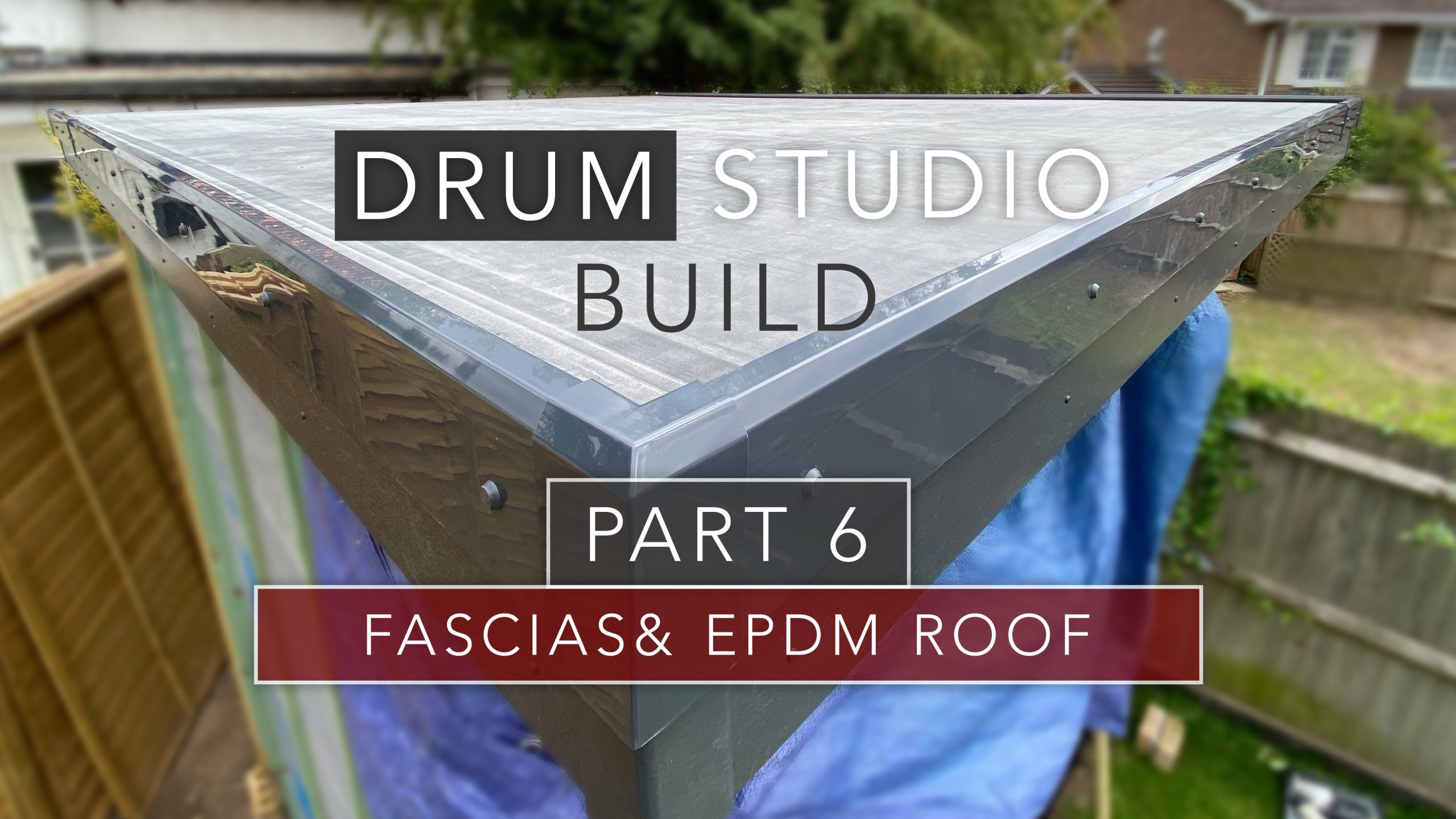
Installing the best roof covering for your garden room – the EPDM Rubber Roof Kit
Contents
Introduction
Welcome to the next part in the series where I’m building a home office and music room in my garden. In this article we will talk through installing the EPDM rubber roof and fascias.
Before you start it is important to give the top of the roof a good brush and a clean to ensure there is no debris.
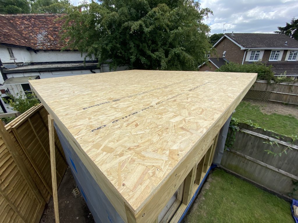
Clean roof, free from dust and debris. Then you should unfold the EPDM roof and lay it over the top for at least a week to allow the material to settle and adapt to outdoor conditions. This is important to ensure shrinkage does not occur, causing the roof covering to fail at a later stage.
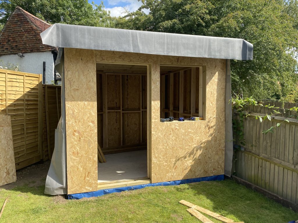
EPDM rubber roof laid over the structure and allowed to settle. Cutting and Preparing the Fascias
The fascia is the trim panel which goes around the edge of the roof frame. This type of roof covering comprises of using two different fascias. The first is your standard construction fascia that you will find in most homes. I have used a 175mm fascia board and used a table saw to cut it down to the correct height.
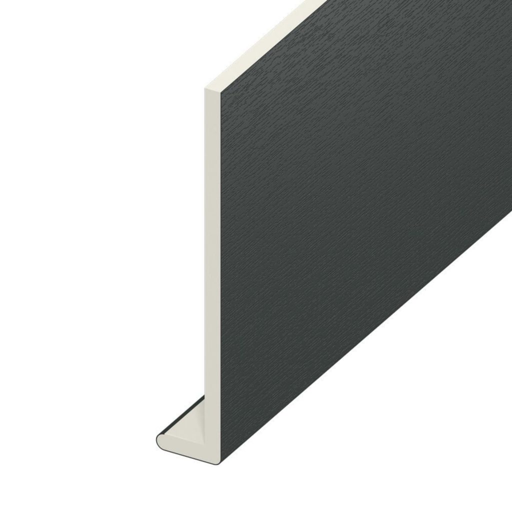
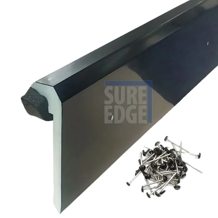
The second part of the facia overlaps this first part and is supplied as part of the EPDM kit.
Fitting Timber Soffits
The soffits are the trim which fix to the underside of the roof frame to cover the overhang. Usually this will also be PVC in keeping with the soffit, but I decided in my car to extend the timber cladding as I feel it has a nice look to it.
The soffit trims are fixed to the underside of the roof structure before the fascia boards are fitted over the top. This is because the fascias have an L shape profile which creates what is known as a drip edge. This allows rainwater to drain off the side of the roof and drip clear of the walls, helping to protect the building from water ingress and prevents staining or damage over time.
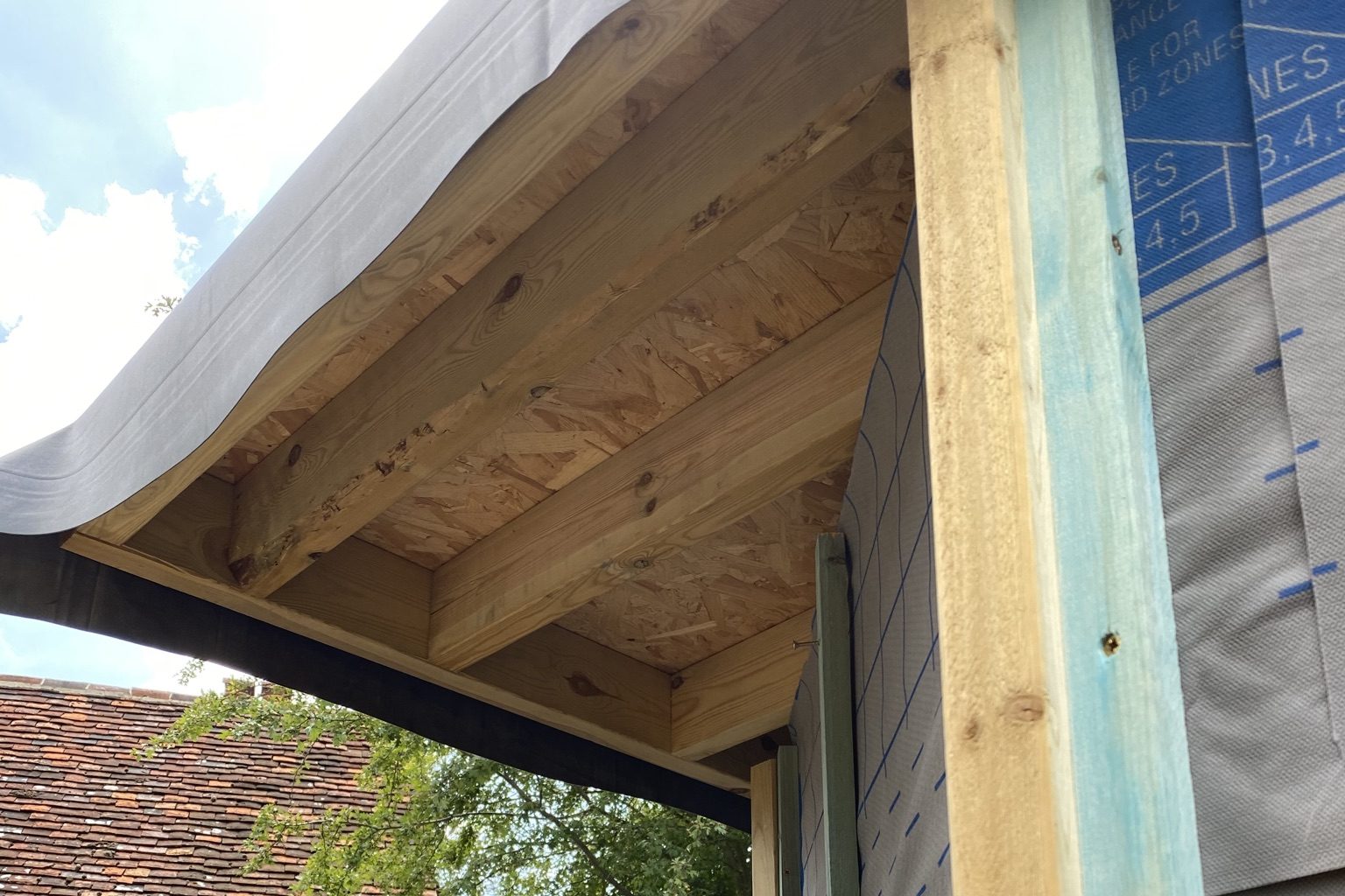
Underside of the rear overhang before soffit panels are fitted. 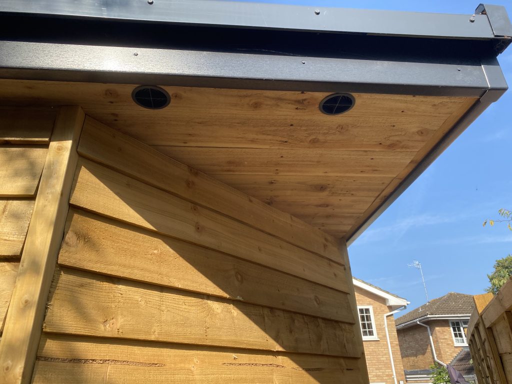
Underside of the rear overhang with soffit boards fitted and air vents With this type of roof construction it is important to add ventilation so that air can circulate above the void in the insulation, preventing condensation build up and eventual rotting of the timbers. Ensure your vents are fixed and aligned in the centers of each pair of roof joists so that every cavity has air circulation. This should result in vents on both the front and the rear overhangs, so ensure you leave enough room.
Fixing the Fascia Boards
Once the soffits were fitted, I moved on to securing the fascias.
Before fixing them in place, I took one of the fascia boards provided from the EPDM kit as a template. These trim panels have predrilled holes for the nail fixings. I lined them up on the fascia boards and marked out the positions to pre-drill the main fascia boards. This way, when both fascias are installed, all of the holes line up perfectly, creating a clean, professional finish.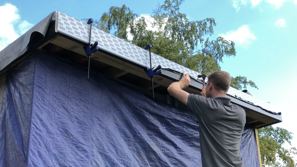
Fixing the facia to the roof frame Adding the Rear Batten and Drip Edge
Before installing the EPDM rubber roof membrane I added a length of the roofing batten along the rear edge and attached the drip fascia part A to this. This is in line with the instructions on the EPDM kit. The reason for doing so is to create a lip where water can run off and land central in the guttering below.

Fixing the roofing batten over the PVC fascia. This setup ensures that rainwater runs off the roof and straight into the gutter channel, preventing it from dripping down the sides of the structure.
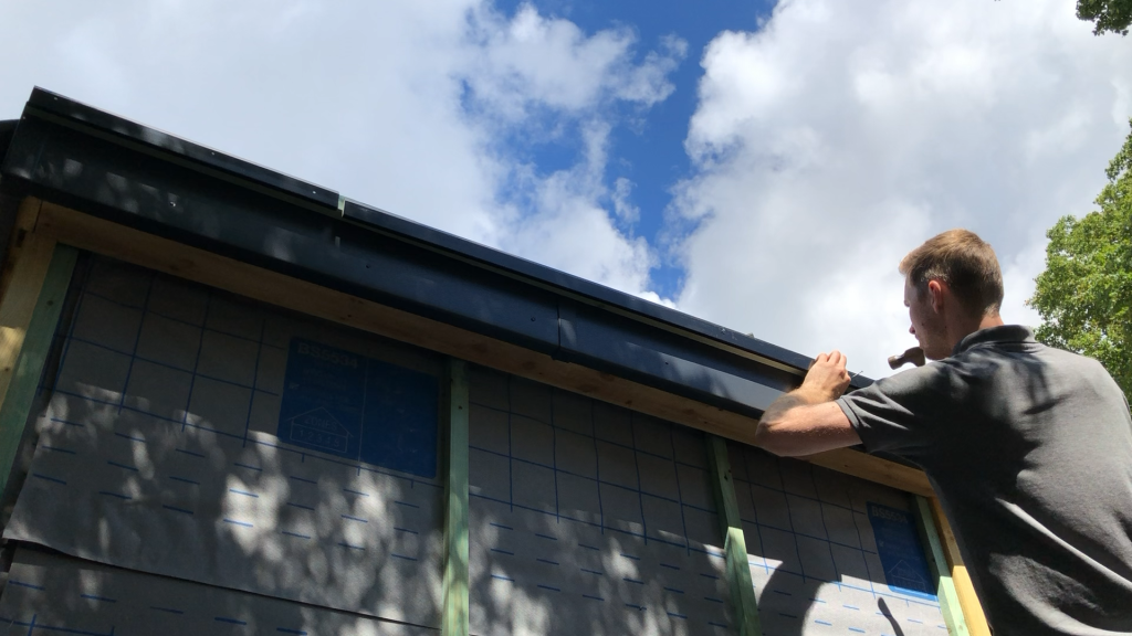
Fixing the underside of the drip edge to the battern. 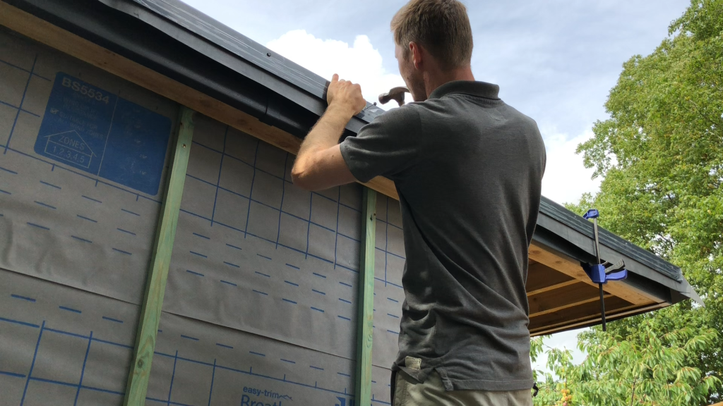
Fixing the second part of the drip edge assembly over the top of the EPDM overhanding from the roof. Installing the EPDM Rubber Roof
With the fascias complete, it was time to start fitting the EPDM rubber roof covering.
EPDM is an increasingly popular option for flat roofs — it’s cheaper than traditional felt, easier to install, and can last up to 50 years, compared to 10–20 years for felt roofs. It does not go brittle, so is less susceptible to cracking and bubbling.
Adhesives and Bonding Process
To adhere the EPDM rubber roof to the roof deck, I used two types of adhesive:
- A water-based deck adhesive applied to the core of the OSB roof surface.
- A contact bond adhesive used around the edges (about 20 cm in from the perimeter).
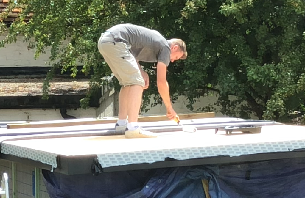
Applying the water based deck adhesive to the OSB boards using a roller. If you’re looking for materials, sites like Rubber for Roofs offer complete EPDM kits that include all the required adhesives and trims. You will also find a link to available kits at the bottom of this article and in the store.
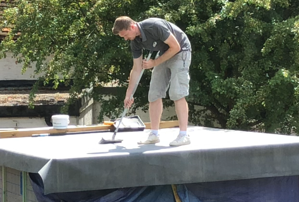
Use a soft bristled brush to ensure there is good contact between the EPDM and the roof, and to ease out any bubbles. 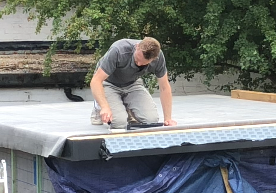
Applying the contact bond adhesive around the edges of the EPDM rubber roof. Once applied, the contact adhesive should be left to go slightly tacky before folding the rubber over and pressing it down firmly.
I used a seam roller to ensure a good, even bond between the two surfaces.
Fitting the Edge Trims
After the EPDM was fully bonded, I installed the second set of fascia edge trims. These trims include a padded compression seal, which ensures the joint is completely watertight and directs all water off the rear of the roof, rather than down the sides.
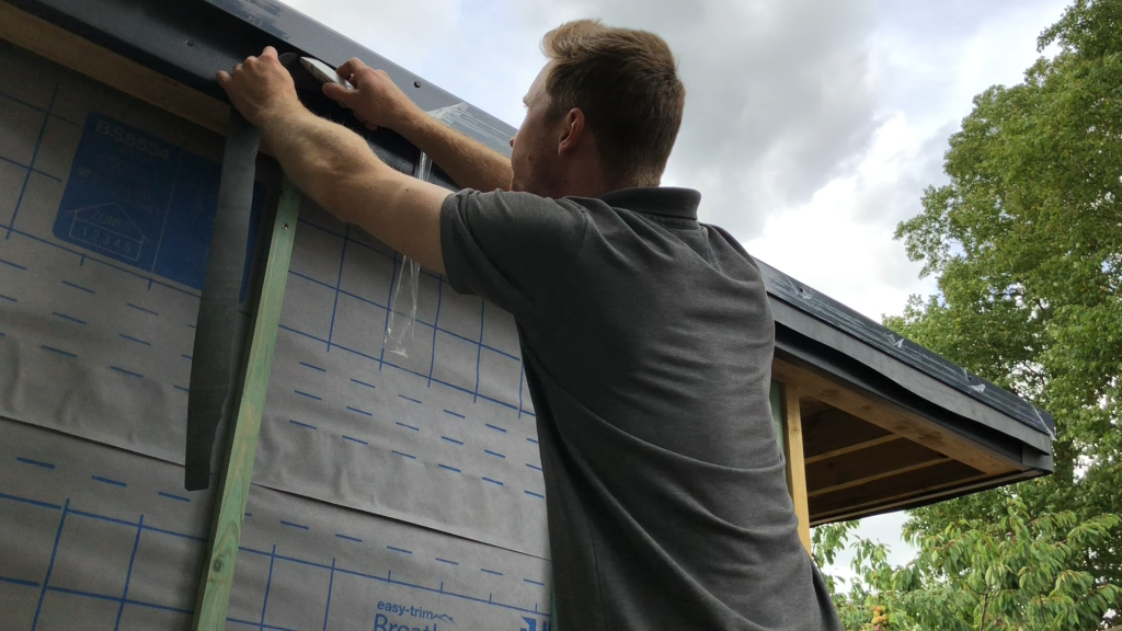
Cutting away excess material from the rear of the building after the second part of the drip edge was fastened. One the trims are fitted, use a stanley knife to cut away the excess rubber.
Fixing Corner Joints and Expansion Gaps
For the corners, I used a product called Mitre Bond to secure the joint covers. The manufacturer recommends leaving a 1 cm expansion gap between joints to allow for thermal movement. When fixing these corners, you should only glue one side of the trim to allow the trim to be albe to move as the roof expands and contracts.
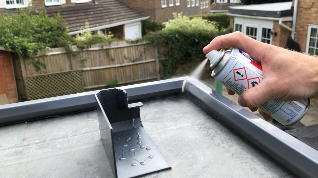
Using the 2 part mitre bond system to glue the corner caps Install the Guttering
I will mention the guttering here as it is the last component to completing the roof, however, you won’t be fixing the down pipe until you have completed the cladding.
The guttering is fairly straight forward, you will find the parts list attached to this article. Attach the gutter to the fascia just below your drip edge from the roof, using the fascia bracket. You will want to inset from of the edge of the roof the outlet so that you can align your downpipe appropriately on the side of the building where you can find suitable fixings. Use two 112.5 down pipe angles with a piece of downpipe cut to length in the middle to bring the downpipe up against the side of the garden room for fixing. Apply the outlet shoe at the bottom.
If you are not sure, looking at the gutting on your own house will likely give you a clear indication of what you need to do.
Final Result and What’s Next
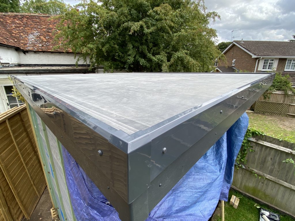
The roof is now complete. Coupled with the breathable membrane on the walls, the structure is now temporarily watertight. In the next part of the build I’ll install the door and window, making the structure completely watertight allowing us to continue with the internals.
If you found this article useful, you can also checkout this section on YouTube and watch the full garden studio build series.
Products Used
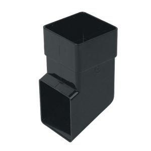
65mm Square Line Downpipe Shoe
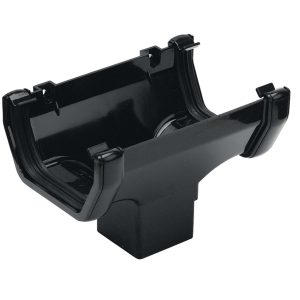
114mm Half Square Line Gutter Running Outlet
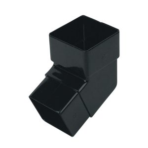
65mm Square Downpipe Offset Bend – 112.5°
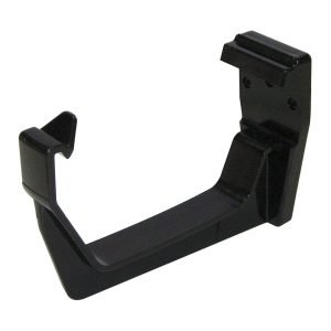
114mm Square Line Gutter Fascia Bracket
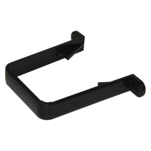
65mm Square Line Downpipe Clip
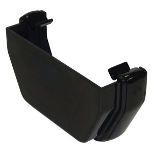
65mm Square Line Gutter External Stop End
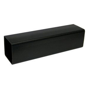
65mm Square Line Downpipe – 2.5m
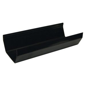
114mm Square Line Gutter – 4m
22mm x 150mm x 4.8m Green Treated Board
Fixing Pins Anthracite Grey – Pack of 50
Fascia Joint Trim Anthracite Grey
Fascia Corner Trim Anthracite Grey
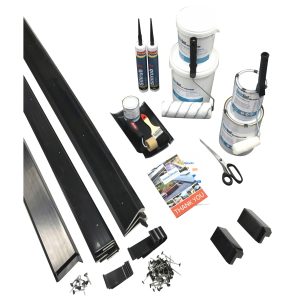
EPDM Rubber Roof Kit with Anthracite Grey Trim
Round Soffit Vent Grey 70mm
PVCu Anthracite Grey Fascia Board

Spax Countersunk Screws – 4x45mm – Pack of 200
-
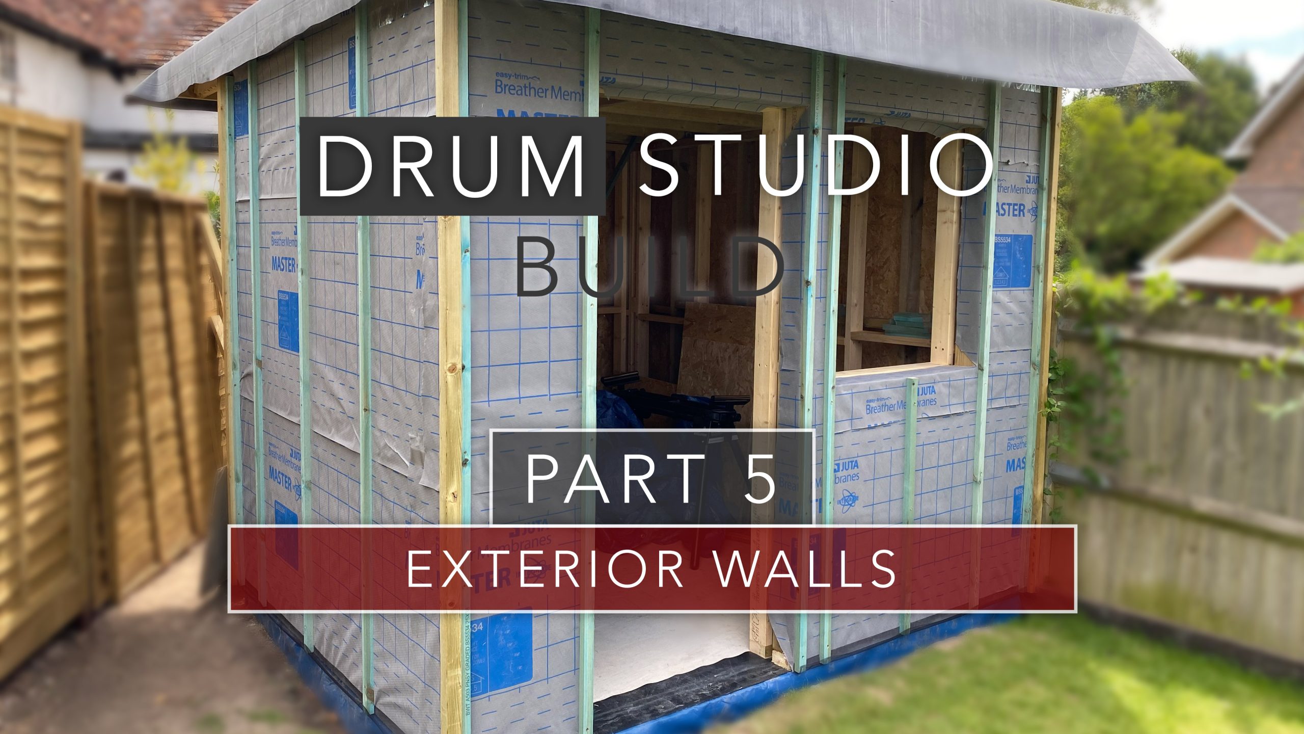
Garden Room Cladding Stage 1: OSB Sheathing, Membrane and Battens Installation
Contents
Introduction
Welcome back to the garden drum studio series. In this stage of the build, I’m focusing on sheathing the external timber frame and preparing the walls for cladding. This includes fixing OSB sheathing boards, adding a breather membrane, and installing vertical battens to create a ventilated cavity behind the final cladding.
These steps are essential for both weather protection and long-term durability, ensuring the garden room remains dry and stable for years to come.
Materials and Tools
For this stage, the key materials used were:
- OSB3 sheathing boards (18mm) — structural-grade, moisture-resistant panels suitable for external use.
- Breather membrane — vapour-permeable yet water-resistant barrier that allows trapped moisture to escape from the wall.
- Treated softwood battens (25mm x 38mm) — create a ventilated cavity between the membrane and cladding.
- Galvanised screws — corrosion-resistant fixings for outdoor environments.
Tools included a circular saw, impact driver, staple gun, and long spirit level.
You can find links to the products I used at the bottom of the article.
Fixing the OSB Sheathing
The first step was to fix the OSB sheathing boards to the external timber frame. Each panel was cut to fit tightly between corners and openings, with staggered joints to improve structural integrity.
Each board was fixed using 45mm screws at approximately 300mm spacing down each stud. This provides both racking strength and a stable surface for the membrane and battens.
As soon as you start to fix the OSB, the entire strength and rigidity of the building takes hold and you’ll find there is no longer any flex or wiggle in the timbers.
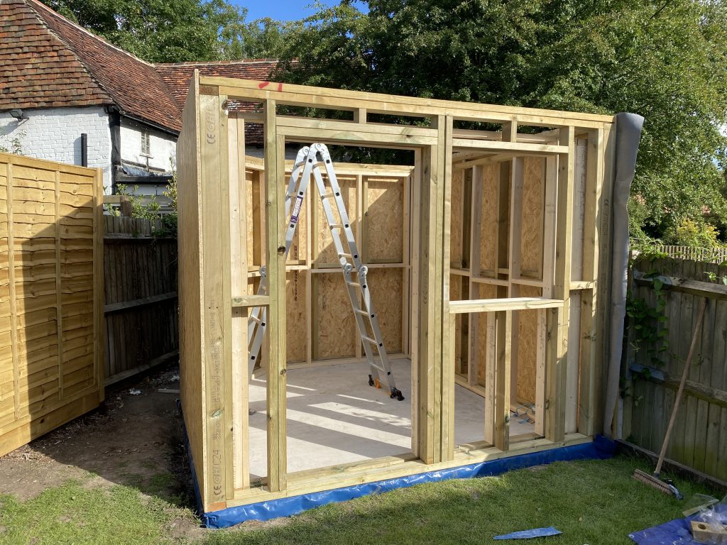
OSB applied to 4 of the 5 exterior walls 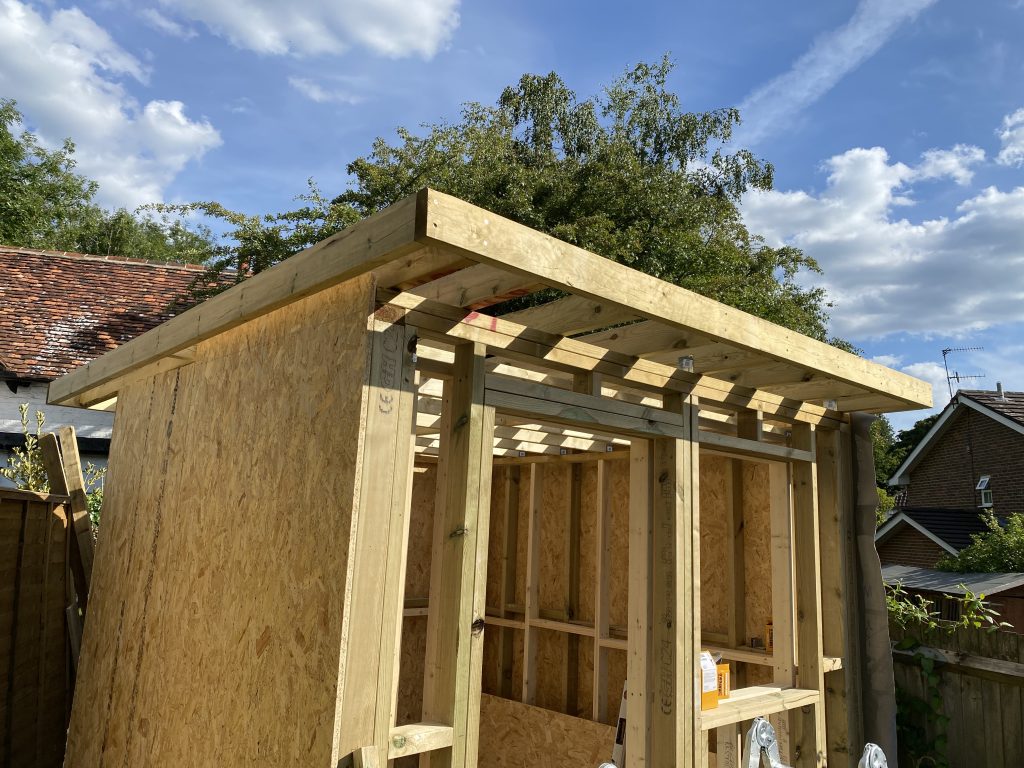
Installing the Breather Membrane
Once all the sheathing was in place, I rolled out the breather membrane, starting at the bottom of the wall and overlapping each course by around 100mm. If you have a join mid width, you should over lap it by a minimum of 200 to 300 cm.
The membrane was stapled securely to the OSB, ensuring it was flat with no wrinkles or tears. The overlaps and edges were sealed with tape which is pre-attached to the membrane, maintaining an unbroken weather barrier.
This layer is crucial for protecting the timber frame from condensation and rot. It prevents water ingress while still allowing any internal moisture to escape, like a one-way barrier.
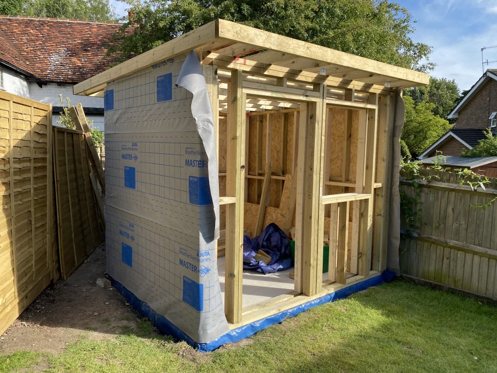
4 of the 5 walls completed with OSB and breather membrane, just the front to go 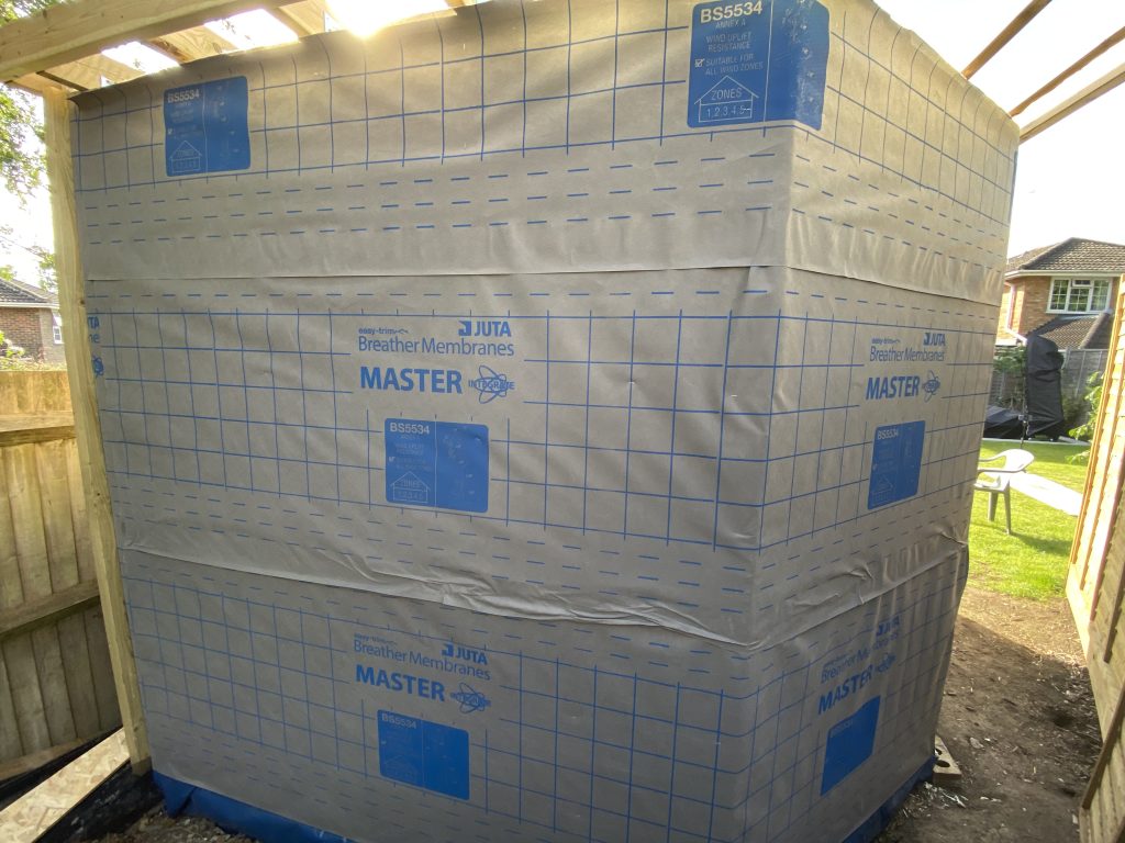
Rear of the garden room with breather membrane applied Adding the Vertical Battens
Next, I installed vertical treated timber battens over the membrane. These are often also called roofing battens. These were fixed in 600mm centers and where possible aligned with the studs behind, allowing me to use 80mm screws to fix straight into the stud work. This might not be a necessary step, but considering the amount of weight that will be attached to the battens, for me it made sense to provide extra resilience by going through into the studwork.
The battens create an air gap of approximately 25mm between the cladding and the OSB. It allows air to circulate behind the cladding, which helps moisture evaporate and significantly extends the life of the timber. This combined with the soffits when ventilation holes are added, will allow for 360 degrees airflow around either side of the cladding, which gives it a fighting chance for maximum longevity.
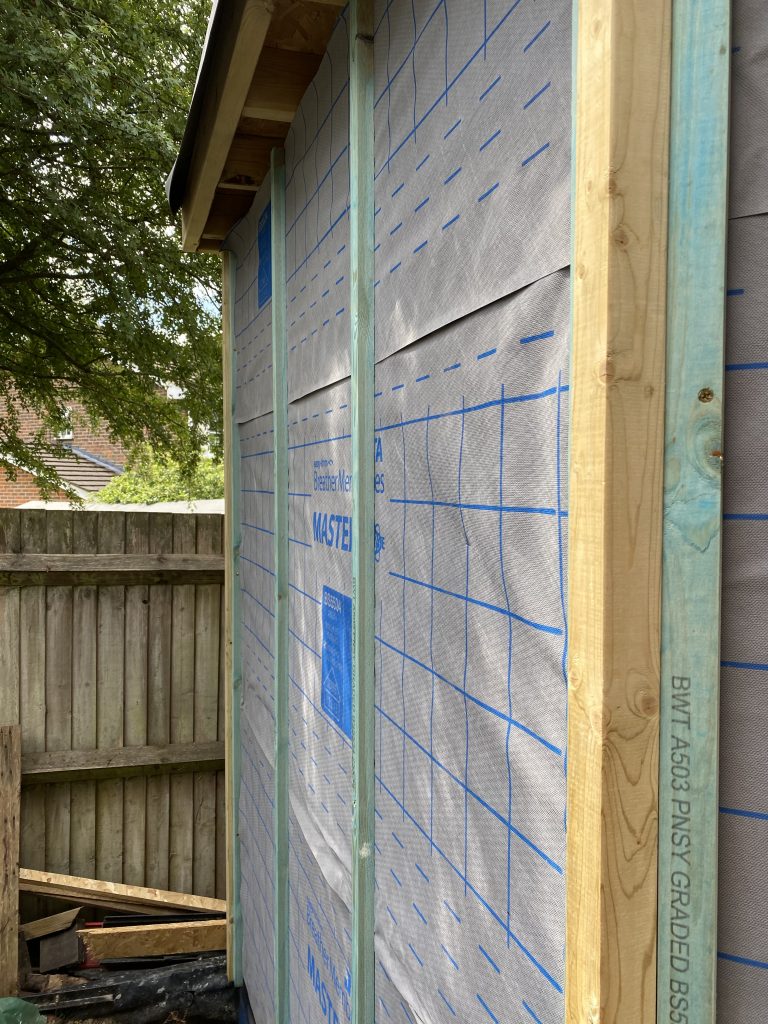
The rear of the garden room ready for cladding Drainage
At the base of the wall, I have added a drainage strip, essentially a small strip full of gravel, basically like a french drain, to allowing any water run off to escape and freely drain away.
Insect Mesh at the Base
One extra step I am taking is to add some insect mesh around the bottom of the battens. This helps stop larger bugs and creatures from making a home in the space behind the cladding.
First I fixed the mesh to the edges of the room using a stapler, applied the battens, and then rolled the mess back over, creating a U shape, and stapled it to the battens.
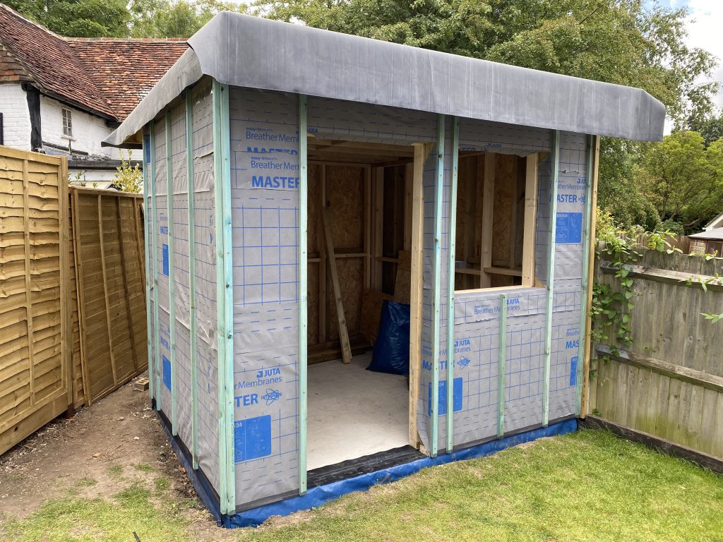
OSB, Membrane and battens applied with black insect mesh stapled around the bottom Corner Trim and Hidden Fixings
The final step before we come onto cladding in a later stage is to fix the corner trim, which is 45mm square pressure-treated timber. I’ve positioned the roofing battens on the edge of each corner so I can fix through the sides of the battens into the corner trim using 80mm screws — meaning there are no visible screws, which gives a nice finish.
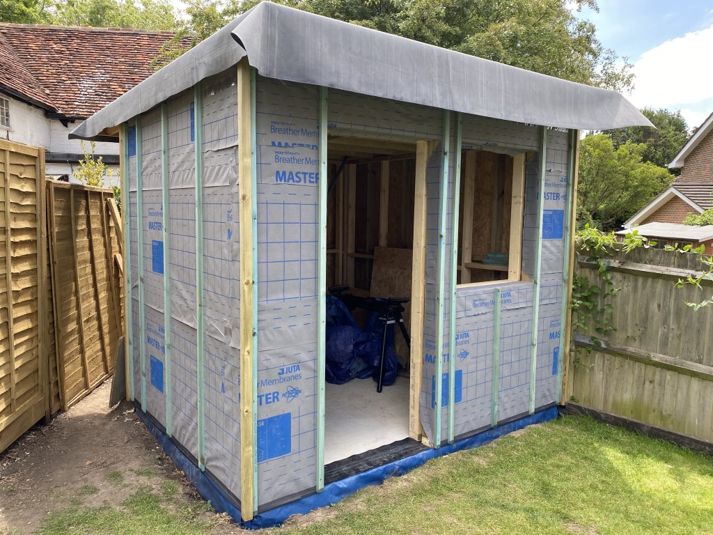
Corner trim now applied, with hidden fixes through the treated battens Garden Room Cladding Options and Finishes
With the wall prepared, the next step will be to apply the final external cladding. Common options for garden room cladding include:
- Featheredge timber cladding — a classic, cost-effective choice with a rustic look. This is the option I went for.
- Thermowood or Cedar — premium finishes that offer greater stability and a natural aesthetic.
- Composite or fibre-cement cladding — low-maintenance modern alternatives.
Conclusion and Next Steps
That wraps up the sheathing and cladding preparation phase of the drum studio build. The walls are now weatherproofed and ready for external cladding.
In the next video/article, I’ll cover installing the EPDM rubber roof before finally coming back to complete the garden room cladding.
Products Used
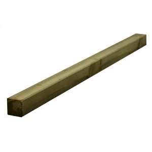
47mm x 50mm x 2.4m Regularised Sawn Treated Timber

Soffit Vent Mesh – 75mm x 30m roll
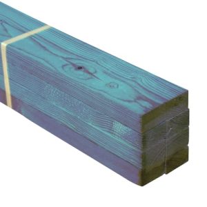
Treated Timber Roof Batten – 25 x 38 x 4800mm – Pack of 8
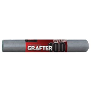
Integrated Breathable Membrane 100gsm – 20 x 1m
Spax Countersunk Screws – 4x45mm – Pack of 200
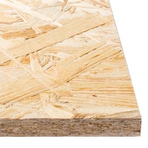
OSB 3 Structural 18mm x 2440mm x 1220mm

Optimaxx Countersunk Screws – 5x80mm – Pack of 350
-
Simple steps for building a flat roof on your garden room
Contents
Introduction
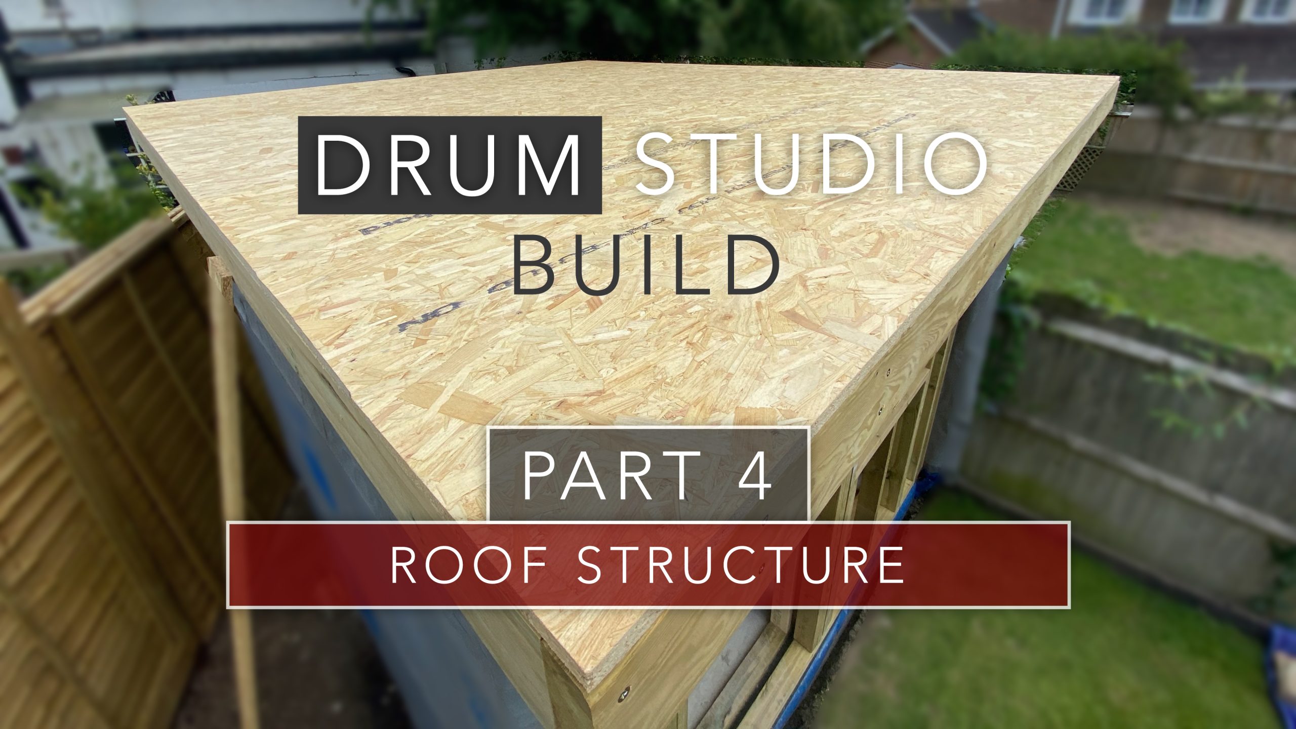
Welcome back to my garden drum studio build series. In this section I’m moving on to one of the most critical structural elements: the flat roof. The garden room roof not only needs to be strong enough to carry its own weight and any loads like snow or tiles, but also has to fit within planning restrictions and contribute to soundproofing performance.
Key Considerations for the Garden Room Roof Design
When planning a garden room roof, there are three main factors to get right:
- Timber sizing and grade: The strength of your roof depends on the timber dimension (e.g. C24 grade 6×2 or 7×2 rafters for spans around 2.5–3m).
- Spacing: Typical rafter spacing is 400mm or 600mm centres. Tighter spacing adds strength, allowing you to use potentially smaller timbers, but uses more of them.
- Slope or pitch: A key decision is whether you will used a pitched roof or a flat roof. Even “flat roofs” need a fall (often 1:40 or 1:60) to allow water to drain off effectively. Planning rules may restrict the maximum overall height, so the slope has to be calculated carefully to still fall within this, but give you sufficient ceiling height.

The roof structure in SketchUp showing the angle of the flat roof pitch Using Span Tables
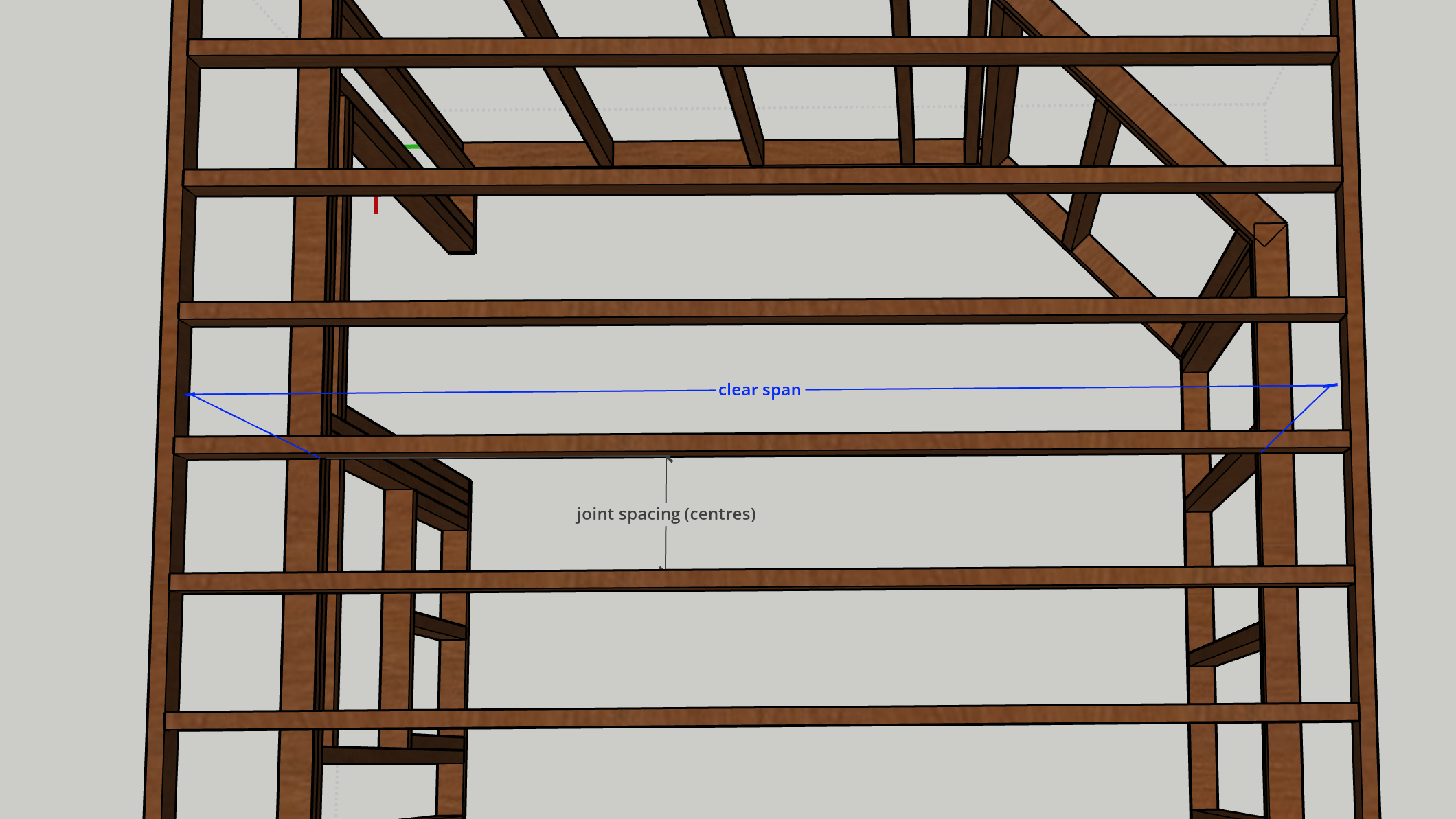
To determine rafter size and spacing, I referred to timber span tables, which are published in UK and EU building regulations. These tables let you cross-check the clear span (distance between walls) with the timber grade, timber dimensions and expected load to ensure your design is safe and compliant.
Timbers are usually structurally graded as C16 or C24, with C24 being the higher rated (and thus usually a more expensive material). If the timbers are not marked with one of these stamps, in accordance to what you planned, you should not use them for structural purposes.
The most commonly referred to reference is the BS 5268-7.2:1989 – “Structural use of timber. Recommendations for the calculation basis for span tables – Joists for flat roofs”. However despite many publications and websites (such as timberbeancalculator.co.uk) using this standard, it is in fact technically withdrawn, replaced with an EU version known as the TRADA Eurocode 5 (BS EN 1995-1-1) “Design of timber structures – General. Common rules and rules for buildings“.
In my case, for a garden room with a span of under 3 metres, C24 125mm x 47mm timbers at 400mm centres are more than sufficient, though always check against the tables for your specific design.
600mm centres are more common, however I would have needed thicker timbers which would have continued to eat into my internal ceiling height in order for me to keep under the 2.5 meter rule. (refer to part 1: Garden Room Design: 5 focus areas to get off to the right start for more information about this). Therefore I went with 400mm centres, which only added a couple of extra lengths of timber to the cost, but saved me an inch of headroom. That may not sound like much, but when the height is already lower than a typical room, every cm adds up!
Building the Flat Roof Frame
Once the design was finalised, I could start to cut the timbers to length for the roof frame. The layout included a slight overhang to protect the cladding, about 20cm at the back, 10cm on the sides, and 40cm overhang at the front.
Depending on the size of your roof, you may choose to build the frame on the ground and lift it into place, or fix the rafters one by one directly to the structure. I decided to make the frame on the ground, leaving out some of the rafters to moderate the weight, and fixed the remaining ones in place once I had the core structured fixed to the roof.
In order to get the pitch that I need, I calculated that I can raise the height of the wall plate on the front wall by the thickness of 1 timber, to give me a fall of 1:80. In an ideal world, I would make the fall larger, but this is the minimum recommended according to BS 6229 on a flat roof and as you know I am trying to keep the height within 2.5m whilst maximising the internal ceiling height. What this ratio means is that for every 80cm of roof, the drop is 1cm. So if the span of your roof is 4 meters, it should be 5cm higher on one end than the other, to give you the minimum fall needed for rainwater run off.
Fixing the Rafters
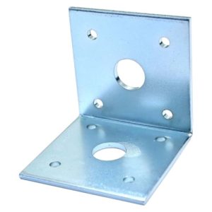
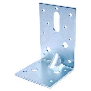
Each rafter was secured to the top plates of the wall frames using L brackets and structural screws. You can also use twist nails. This provided both vertical and lateral stability. There are other methods, such as notching the rafters to sit within the wall frame top plate, and fixing directly with multiple screws or nails, but personally I found this approach to be cleaner and less time consuming.
I also added noggins (short pieces of timber between the rafters) to reduce twisting, provide rigidity and also extra fixing points for the decking board.
If you are building a ‘room within a room’ and have a second internal ceiling, it is just as important to add the noggins through the centre for rigidity, but also to add some around the edge. This will give you useful fixing points when it comes to add the plaster board later.
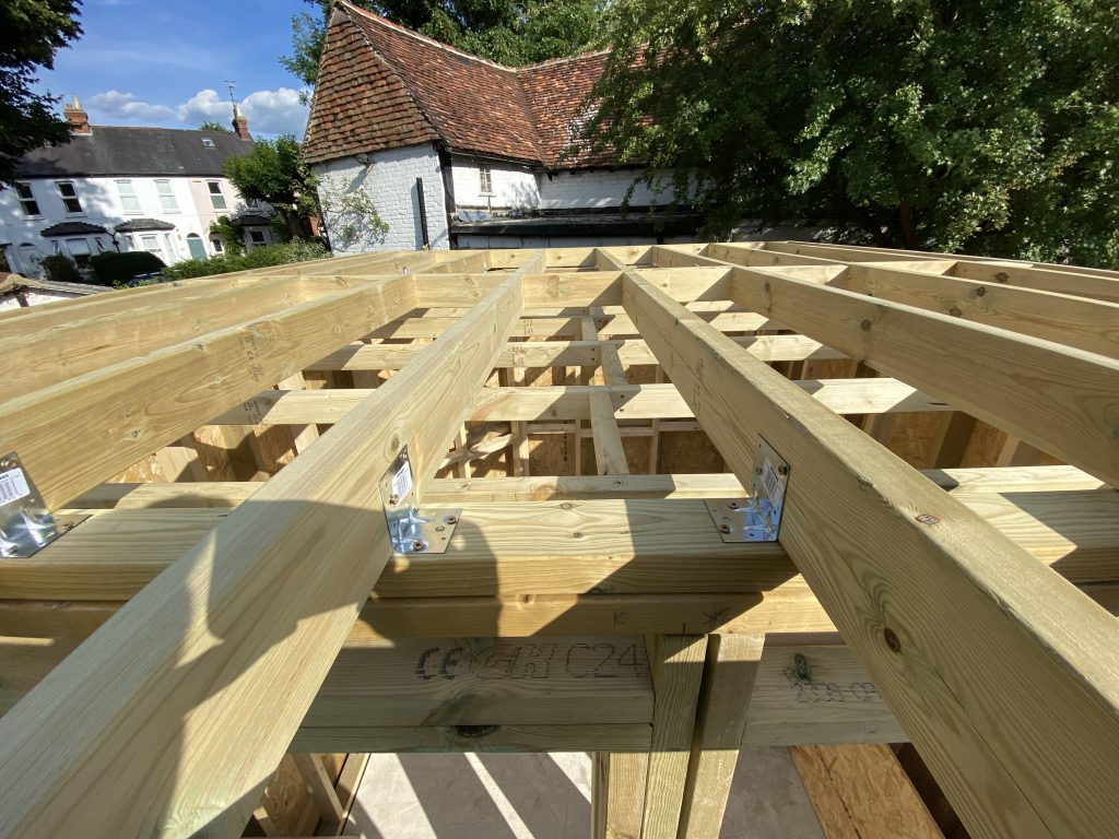
External view of the ceiling rafters, showing the L bracket fixing plates 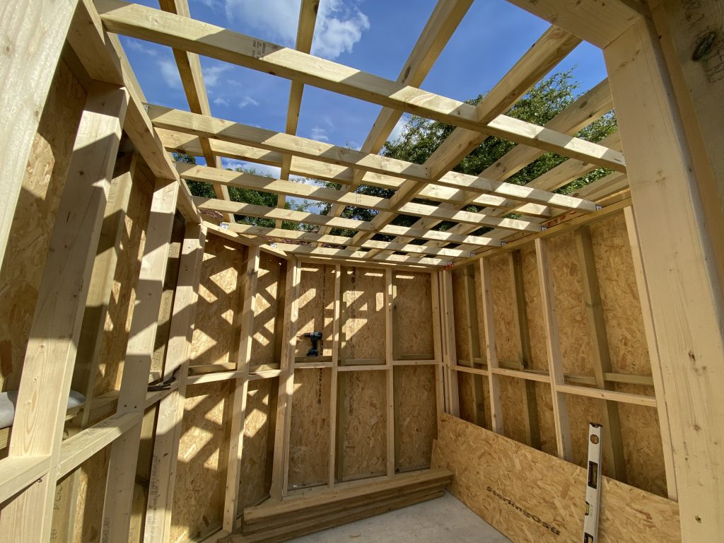
Internal view of the ceiling rafters Adding the Roof Decking
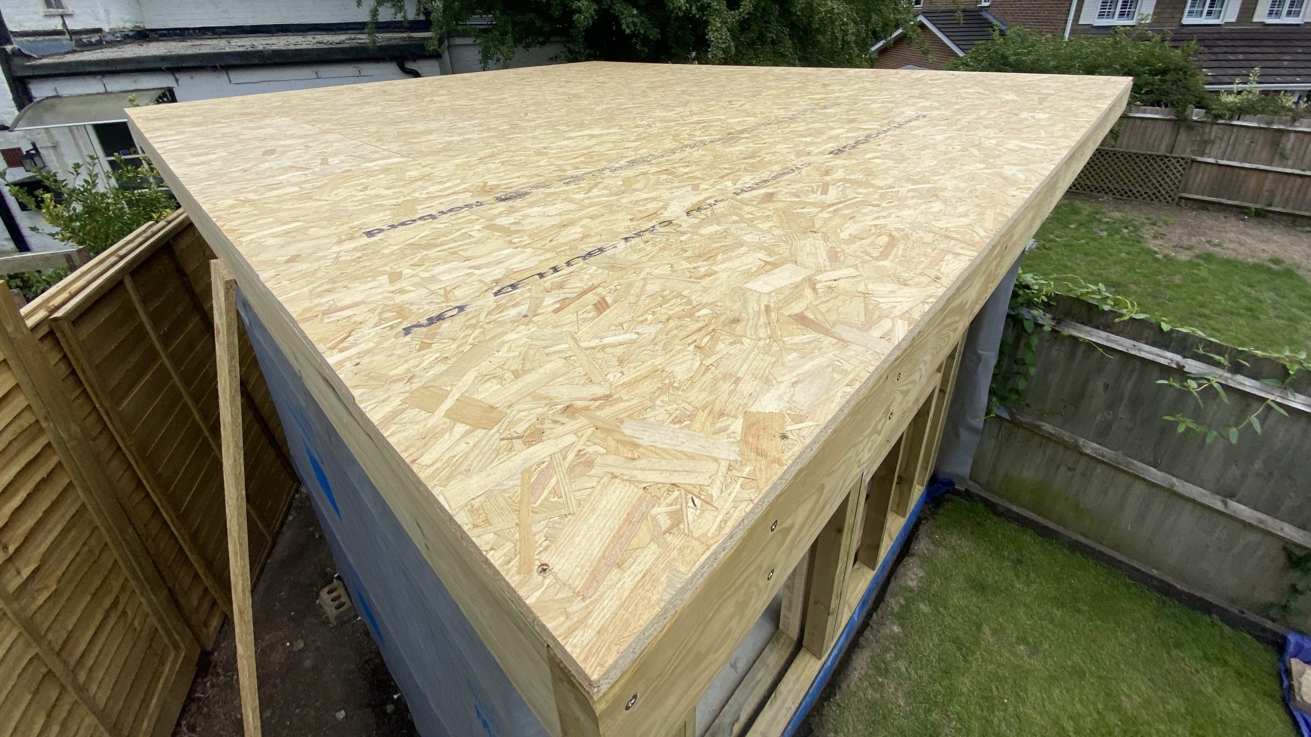
The decking layer was made from 18mm OSB3 tongue-and-groove boards, which are semi moisture-resistant, structural grade and designed for roofing and siding. They were laid perpendicular to the rafters and staggered for strength. Fixed down with screws 45mm screws, with roughly 30mm spacing per screw along on each rafter.
Weatherproofing the Roof
For the final covering, you can choose EPDM rubber (most popular today for flat roofs), felt, or fibreglass GRP. In my case, EPDM was the preferred choice because of its long lifespan (over 20 years), easy installation, and seamless finish (no joins). Check out chapter 6 for the detailed process.
Conclusion and Next Steps
That completes the flat roof structure for the garden drum studio. In the coming stages, I’ll add the roof covering, insulation and several internal layers to improve both thermal performance and soundproofing.
If you found this article useful, you can also checkout this section on YouTube and watch the full garden studio build series.
Products Used
Angle Bracket 50 x 50mm
Spax Countersunk Screws – 4x45mm – Pack of 200
C16 75mm x 47mm x 3.6m Regularised Treated Sawn Timber
OSB 3 Structural 18mm x 2440mm x 1220mm
Angle Bracket 90 x 60mm
C24 125mm x 47mm x 3.6m Regularised Treated Sawn Timber
ForgeFix Single Thread Screws – 5x100mm
Useful Links
Information on building regulations with regards to materials, and a useful span table calculator:
Span Tables Calculator https://www.timberbeamcalculator.co.uk/en-gb/span-tables/ BS 5268 https://knowledge.bsigroup.com/products/structural-use-of-timber-recommendations-for-the-calculation-basis-for-span-tables-joists-for-flat-roofs TRADA Eurocode 5 https://knowledge.bsigroup.com/products/eurocode-5-design-of-timber-structures-general-common-rules-and-rules-for-buildings BS 6229 https://knowledge.bsigroup.com/products/flat-roofs-with-continuously-supported-flexible-waterproof-coverings-code-of-practice -
Easy guide to build interior and exterior timber framed walls for a garden room
Contents
Introduction
In this post I’ll be covering how I built the timber framed walls for the garden room. There’s quite a lot to do because we’re constructing a “room within a room,” which means two separate wall structures: both the external frame and the internal frame.
Using SketchUp to design your timber framed walls
Before starting construction, I used SketchUp’s “dimension” tool to create accurate plans of each wall, including every measurement for every component and negative space. I took a screenshot of each wall panel with the dimensions applied and printed it. This made the whole process far more efficient, for sure saved time when it came to cutting and assembling the frames. I would recommend SketchUp if you’re considering a similar build and doing a similar exercise.
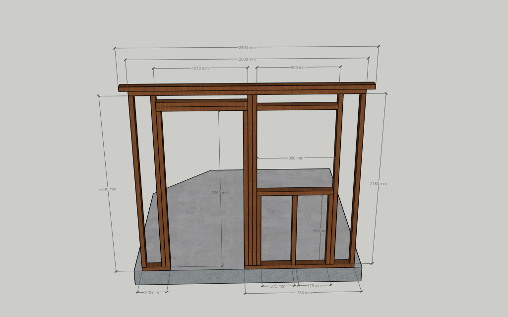
Example mark up of the front external wall in SketchUp with dimensions. Cutting the Base and Top Plates
I started off by cutting the base plates for each exterior wall, marking each joint, and drilling holes for fixing bolts to the concrete foundation. The best method for this is to push the timber down on top of the bolt studs to leave an impression, then you have the exact location to drill the holes. Once that was done, I made identical copies of these timbers for the top plates. I then cut the supporting studs to size, ready for assembly.
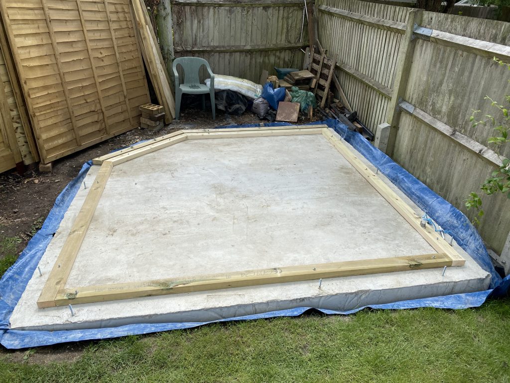
Test fitting the wall plates to the concrete slab and cutting holes for the fixing bolts Assembling the Stud Walls
With all the timber cut, it was time to assemble the stud walls. Each stud was carefully measured and positioned to ensure the walls would align perfectly once raised.
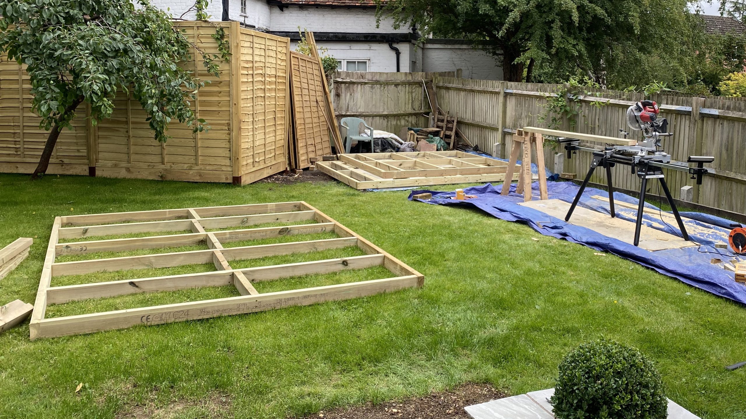
Constructing the wall frames 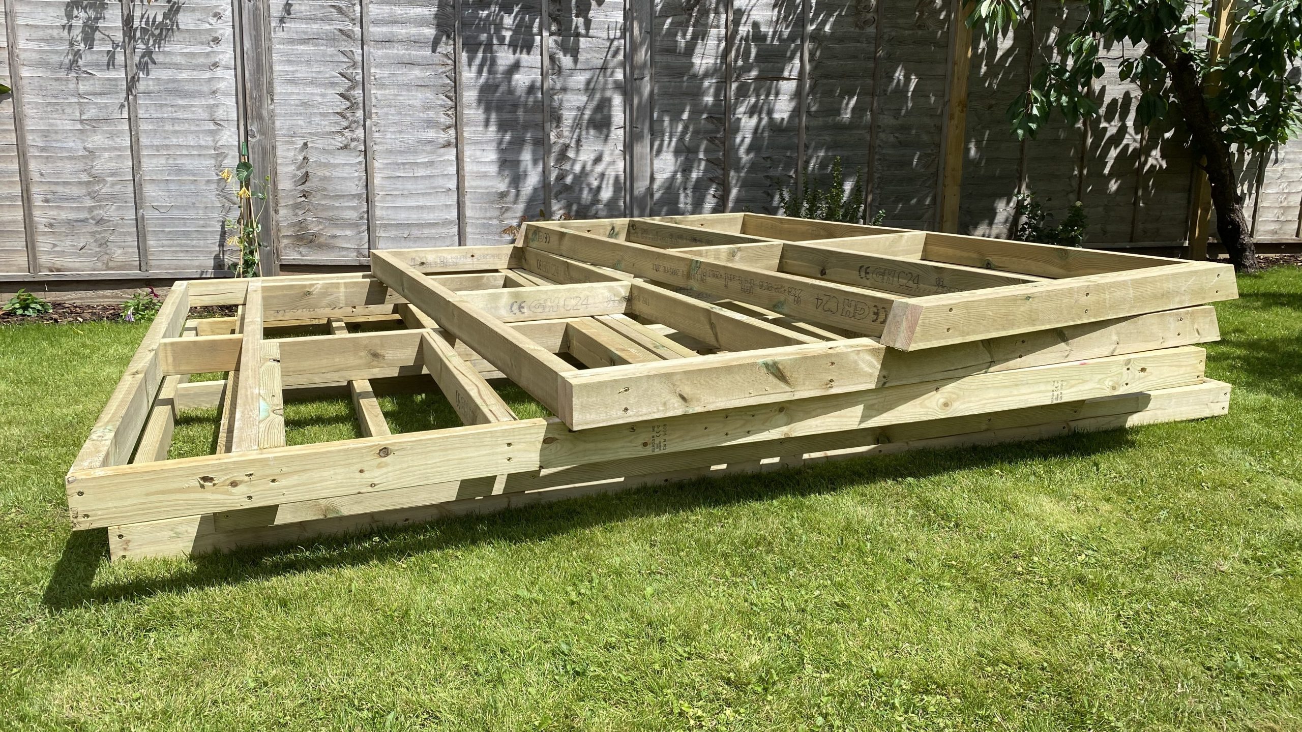
Completed exterior wall frames, ready to be fastened together Damp Proof Course
It is important (and standing building practice) to use a damp proof course between the concrete and the timber. This layer prevents any water from rising up through the concrete overtime and being absorbed into the wood. I also used a layer of silicon to help prevent any water entering the room sidewards.
External Walls
I raised each wall in turn, fixing them securely to the base plates and adding a fixed or two to keep them supported. Once all the walls were up, I ensured they were square and plumb. Cross-bracing helped maintain stability as the structure began to take shape.
I used external grade / treated C24 timber for the frame as this is best practice for external walls to help protect against moisture. Specifically I used 100mm x 47mm, and generally bought in 2.4m, 3m, or 4.8m lengths. I used 5mm x 100mm screws for fixing the timbers together.
Internal Walls
Next came the internal frame — the second “room” of the room-within-a-room design. This inner wall was set slightly inside the external frame to maintain the air gap, which is crucial for this soundproofing technique. I repeated the process of cutting, assembling, and raising the internal walls.
In terms of timber, I used treated timber for the baseplate, but ordinary untreated ‘CLS studwork’ timber for the internal walls. I used 5mm x 80mm screws for fixing, as the CLS timbers are smaller dimensions compared to the regularised treated timber.
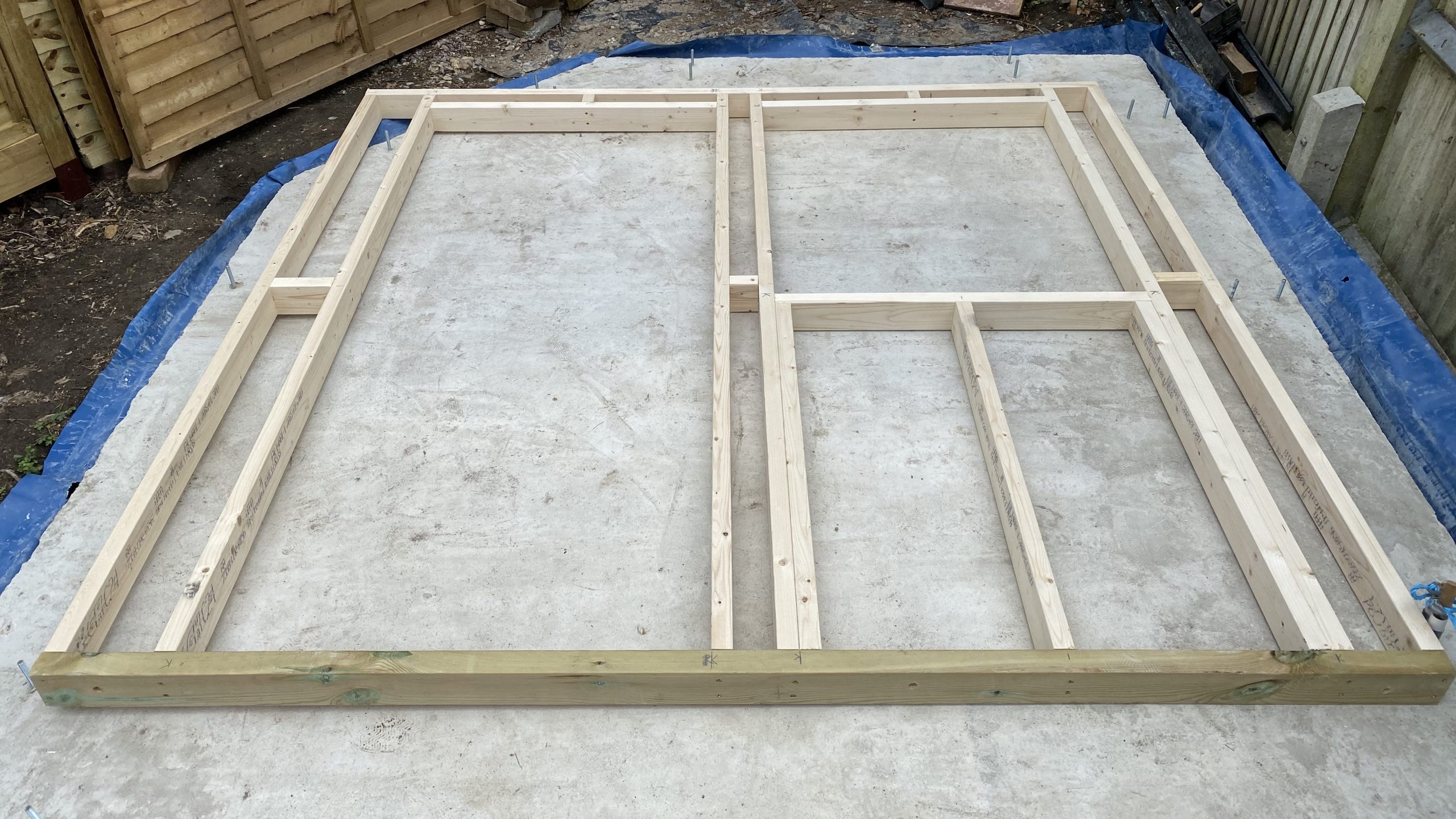
Assembled internal wall frame for the door / window section Soundproofing Considerations
This double-wall system is the core of the soundproofing design. By separating the internal and external walls with a small gap, vibrations and noise transfer are reduced. In later stages we will add sound insulation and sound plasterboard layers to further improve acoustic performance.
Conclusion and Next Steps
With both sets of walls complete, the studio’s main structure is now visible. The next stage will focus on the roof construction and additional soundproofing measures.
You may notice in the below picture that one wall is already clad with OSB. In fact, I have fully completed this exterior panel as access to the side is very limited with the fence. You can skip to part 6 to see the start of the cladding process.
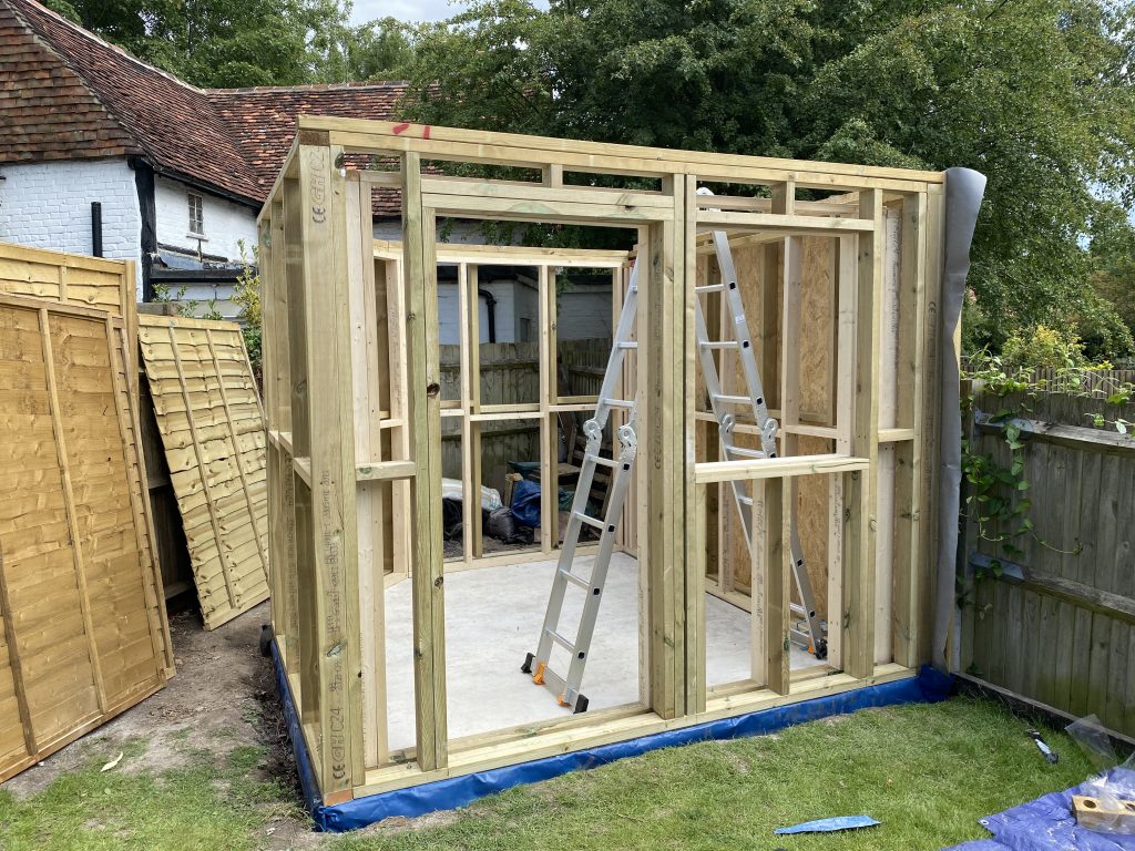
Completed internal and external timber framed walls Products Used
Optimaxx Countersunk Screws – 5x80mm – Pack of 350
Soudal 270ml Multipurpose Clear Silicone
38mm x 89mm x 2.4m CLS Studwork Timber
C24 100mm x 47mm x 3m Regularised Treated Sawn Timber
C24 100mm x 47mm x 2.4m Regularised Treated Sawn Timber
ForgeFix Single Thread Screws – 5x100mm

DPC Damp Proof Course
M10 130mm Carriage Bolt and Nuts
-
The ultimate how to guide for building a concrete slab base for your garden room
Contents
Introduction
There are several types of foundation you can use for your garden room, including a concrete slab base, ground srews, brick pillars and others. I decided the best option for my situation was a concrete slab base. In this article I will show you the steps I took to get to the finished article.
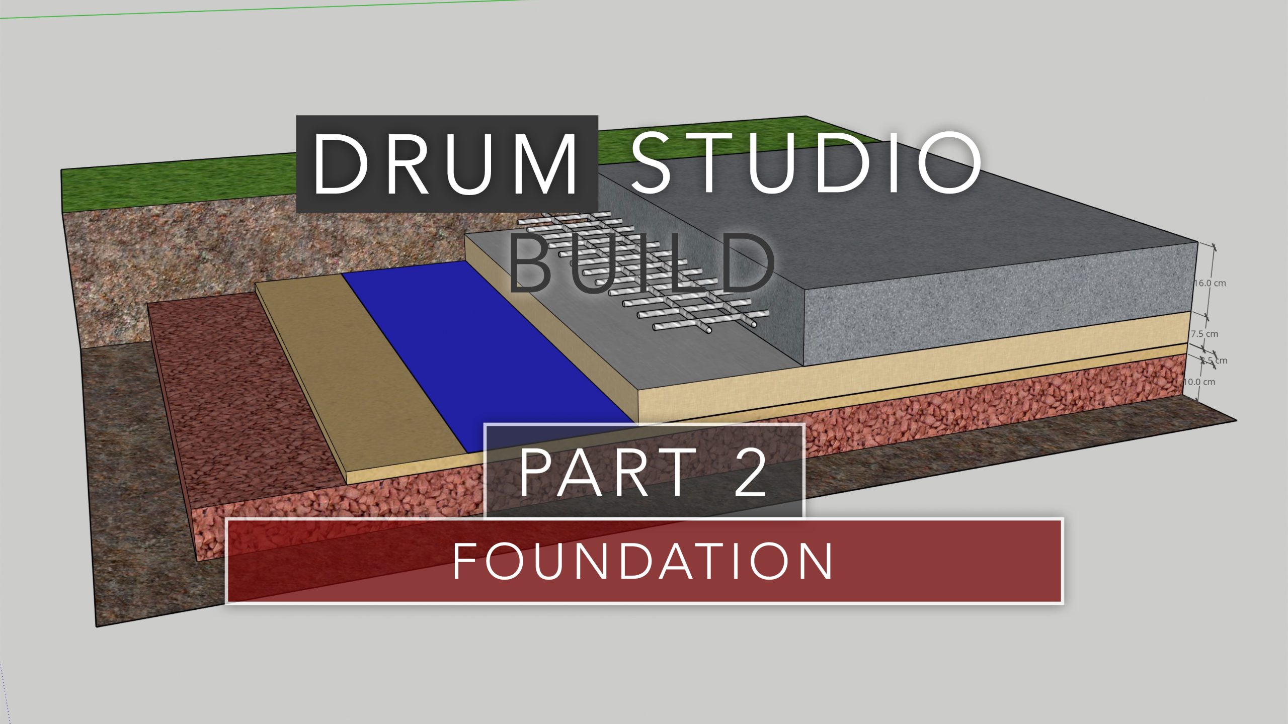
In summary, I started off by digging a hole about 350mm deep. I filled it with 100mm of compacted hardcore, followed by 25mm of sand. On top of that went a damp-proof membrane, 75mm thick insulation, and A142 mesh (also known as concrete rebar). Finally, I poured in Ready Mix C25 cement.
You can see approximately the thickness of each layer in this cross-section of the concrete slab base below. That’s the theory — now let’s get into the actual build.
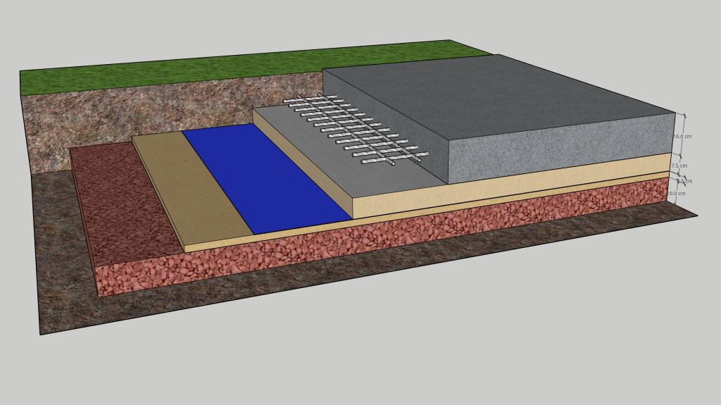
Cross section of the foundation used in this build: a concrete slab base Digging the Foundation
Pretty straightforward, not much else to add. Mark out the location of where your garden room will be located, and dig a hole!
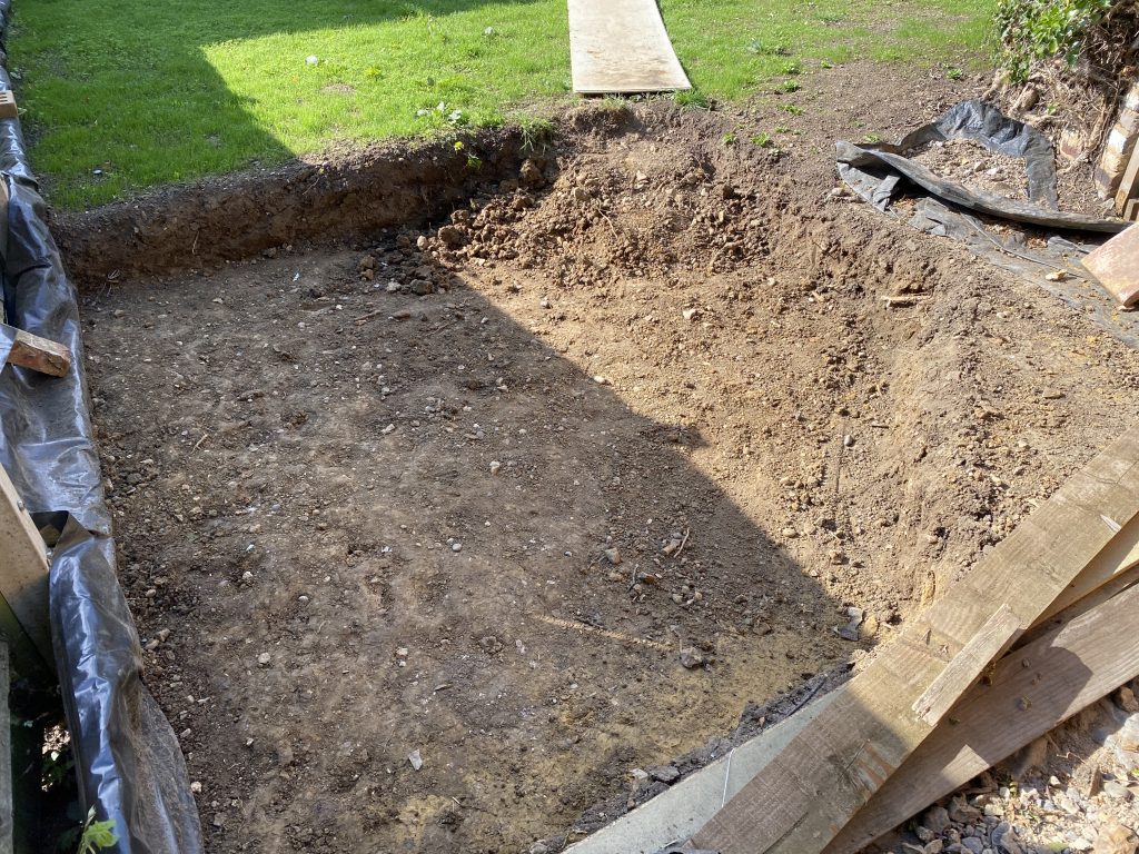
Dig out almost completed Creating the Frame (Shuttering/Formwork)
Now that the hole is dug, the first step is to insert the frame — also known as shuttering or formwork. This sits inside the hole and creates a structure for the concrete to be poured into. Once the concrete slab base is cured, we will remove the frame.
After a test fit, I realised I needed to chip away at the edges a bit more to get a snug fit. Once the frame was in place and level, I started backfilling with MOT Type 1 hardcore.
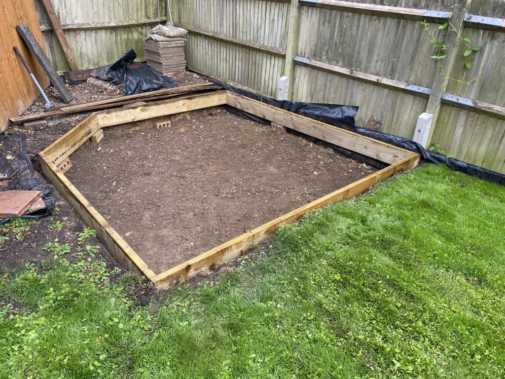
Shuttering in place, with bricks holding it to the correct level Compacting the Hardcore
With the MOT on site, I levelled it out to form a solid base for the next layers. Due to the coronavirus lockdowns, I couldn’t get a compactor, so I improvised using a lump hammer — surprisingly effective.
It’s important to use proper materials and not just rubble or old bricks. Compaction ensures there are no air gaps, which can otherwise lead to movement, settlement, or cracks in the concrete floor later.
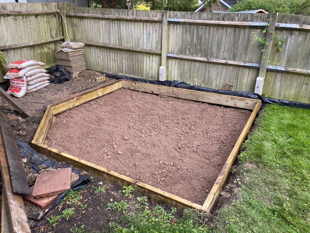
MOT before compaction 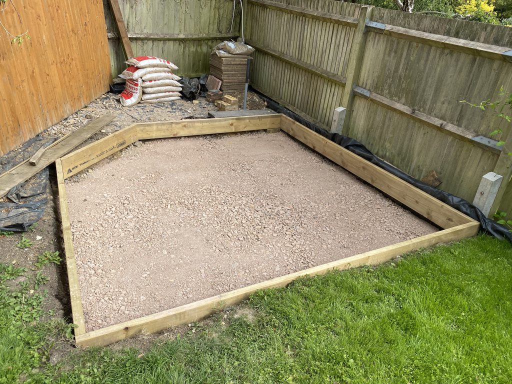
MOT after compaction Laying the Sand and Damp-Proof Membrane
The next step was to add approximately 25mm thick layer of sand. This provides protection for the damp-proof membrane, which goes on next. The sand helps prevent sharp objects from puncturing the membrane and ensures it remains effective.
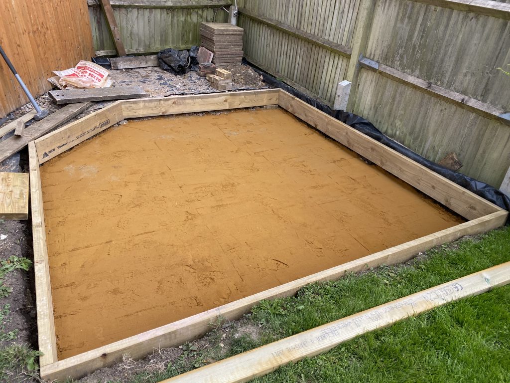
Adding a layer of sand smooths out the bumps and provides a protective surface for the damp proof membrane 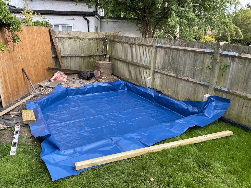
Damp Proof Membrane added and roughly trimmed Why I Chose a Concrete Slab Base
One key reason I’m using a concrete base is to maximise ceiling height. Planning restrictions limit overall height, so by embedding the base close to ground level and insulating beneath it, I can keep the internal floor low and gain valuable headroom.
Adding Insulation and Sealing Joints
I installed 75mm Quinn Therm insulation beneath the concrete for thermal efficiency. To improve performance and prevent concrete from seeping through gaps, I sealed the joints with aluminium foil tape, forming a continuous barrier.
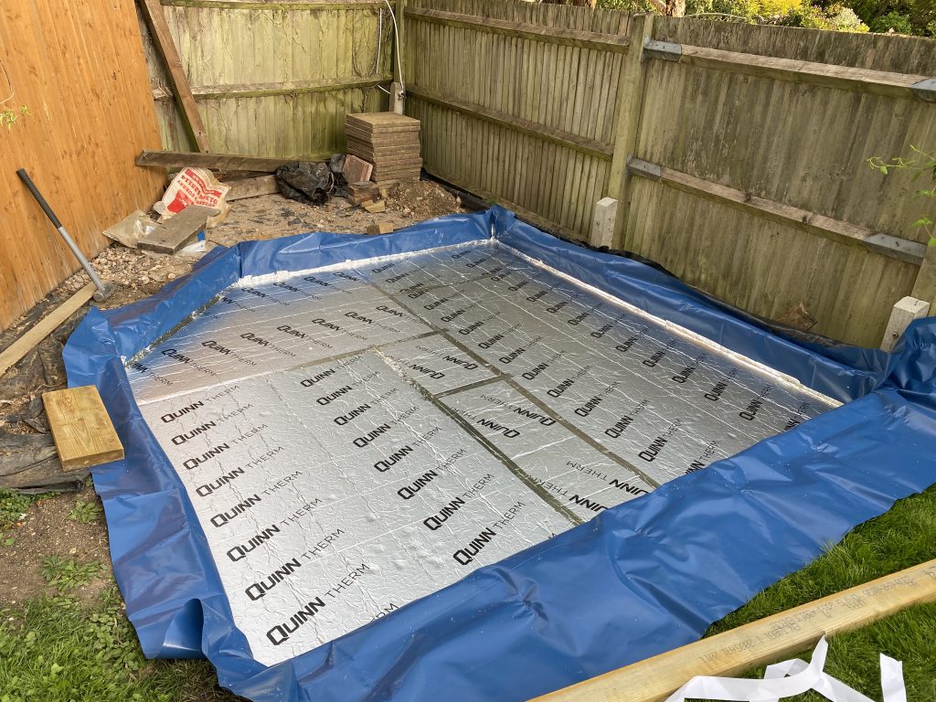
Insulation layer added and joins taped up Reinforcement Mesh Installation
I cut the A142 steel mesh to size. If you don’t have an angle grinder, you can use a hack saw. Each panel is 3.6m x 2.2m with 200mm apertures and 6mm thick bars — more than enough for this project. I raised the mesh off the ground on broken bricks (6–8cm) to position it a third of the way up from the slab for optimal strength. You can get purpose designed risers, but for the size of this project the bricks will surface.
I then tied the pieces together using wire and secured the ducting in place. It’s also important to leave around 10cm clearance from the mesh to the slab edges.
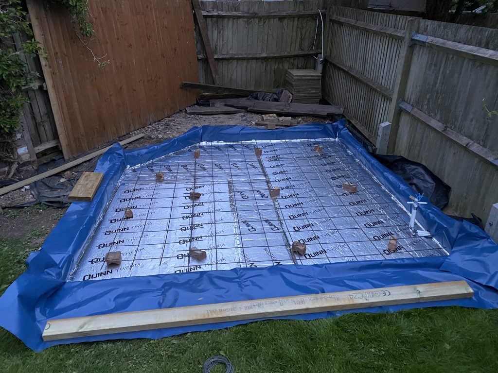
Adding the mesh, using old bricks as risers Planning for Services (Electrical Ducting)
Before pouring concrete, I installed plastic ducting to run electrical cables through the base and into the studio. I used two 20mm plastic pipes — one for power and another for future expansion so I wouldn’t need to drill through the slab later. I fed some nylon rope through to make it easy to pull utilities through.
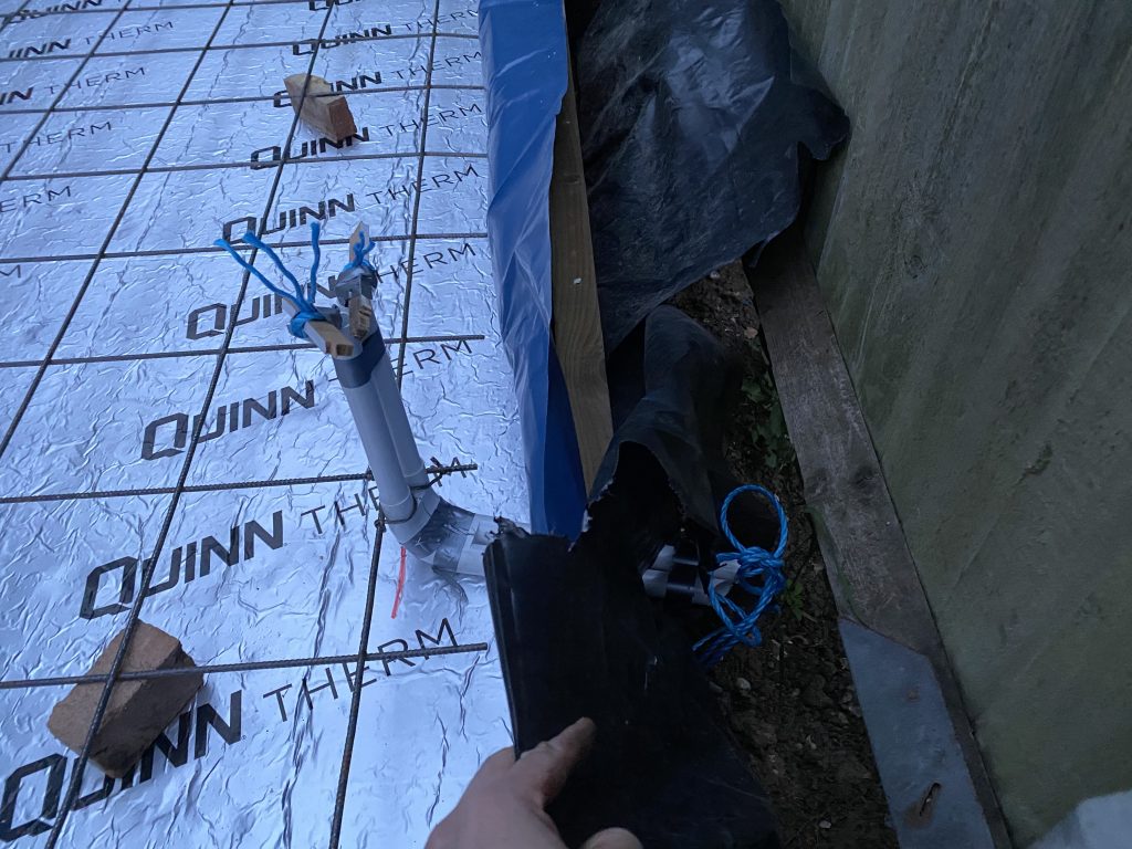
Adding pipework for services Pouring the Concrete
With everything in place, I poured C25 grade ready-mix concrete. The mixer was at the front of the property, and we barrowed it around to the back. I used around 1.5 cubic meters in total.
To level the surface, I used a long, straight piece of timber and smoothed it out for a flat finish.
Fixing the Anchor Bolts
Before the concrete cured, I installed anchor bolts around the perimeter to secure the timber frame / wall plates. I had previously measured and marked bolt positions using a wooden template to ensure perfect alignment with the future stud work. This helped avoid any clashes and ensured the frame would be stable. You can use concrete fixings, but this ultimately is stronger.
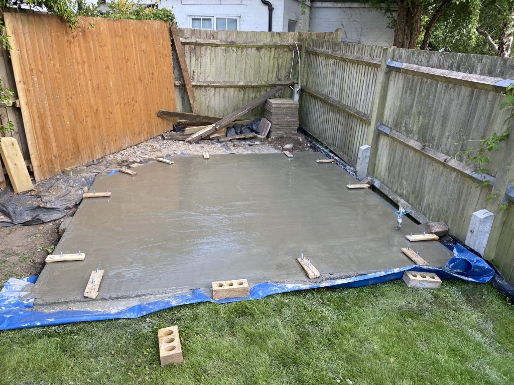
Freshly poured and smoothed over concrete Final Finishing
After placing the bolts, I used a trowel to finish smoothing the slab. While it’s a rustic finish, it’s more than adequate for the job and gives a solid base for building the studio.
Conclusion and What’s Next
Here is the final product — one week after pouring the concrete, I removed all the shuttering. The base is now complete, and we’re ready to move on to the next phase: building and fixing the walls. Remember whilst the concrete is curing it is important to keep it damp to stop it drying out too fast. Keep a tarpaulin over it, and if it is particularly hot water, make sure to lightly water the slab.
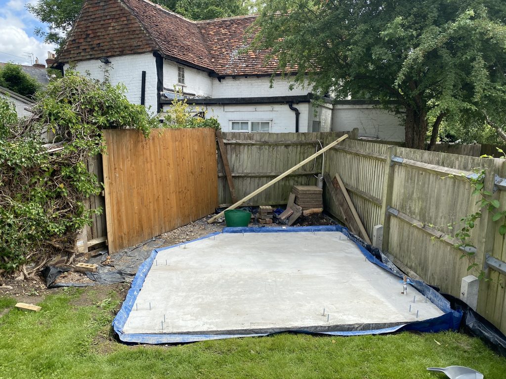
The finished concrete slab base, complete with bolts
Products Used
ForgeFix Single Thread Screws – 5x100mm
C24 200mm x 47mm x 4.8m Regularised Treated Sawn Timber

MOT Type 1 Sub Base Jumbo Bag

Building Sand
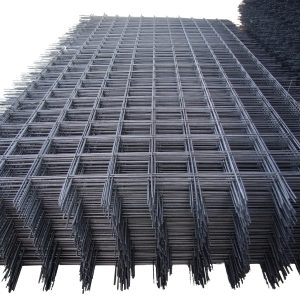
Concrete Reinforcement Steel Fabric Mesh
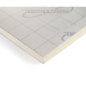
PIR Insulation Board 70mm x 2400mm x 1200mm
M10 130mm Carriage Bolt and Nuts

Damp Proof Membrane 1200g 5M X 4M

Aluminium Foil Tape 48mm x 50m
-
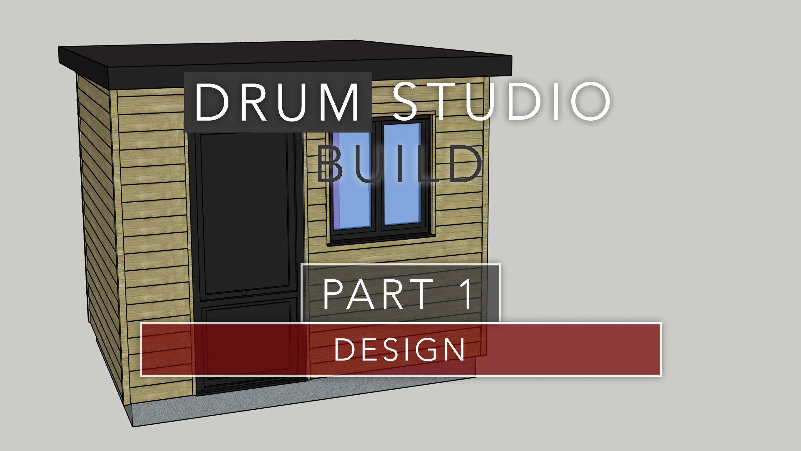
Garden Room Design: 5 focus areas to get off to the right start
Contents
Introduction
Hello and welcome to the first part in a new series where I’m going to take you step by step through my garden room self-build. This garden room is a little more special, as it’s going to adopt some soundproofing techniques and be used as a drum practice studio.
This series has started out as a channel on YouTube and i’ve now combined it with another passion of mine, web development, to create this informative website providing additional content and information on the builds.
In this video and article, I’m going to talk about some key areas you are probably thinking about but not sure where to start when it comes to the garden room design and build, including planning permission and building regulations. I will also talk through my initial garden room designs.
Throughout the video I will show you some of the tricks and techniques i’ve used to maximise every cm of space when it comes to the construction and choice of materials.
Aims of the Project
Creating a sound proof practice space is a common dilemma amongst drummers and musicians in general. The common question is always asked, I wonder if I could soundproof my shed or garage? Well the best solution is to create a dedicated space.
I’ve you’ve looked into garden rooms then you’ll know they can be very expensive, particularly if you need to add soundproofing. There are some nice options out there, but, if you are a dab hand at DIY, do your research and invest in some basic tools, you’d be surprised how much you can do yourself. I’ve estimated my build will cost between a quarter and a third of the price to have one professionally installed. The only area where I will be seeking professional help is for the electrics, due to regulations. More on that later.
Once completed, I hope that the space is large enough to be functional, and the sound proofing is sufficient to keep disruption to the neighbours to a minimum. You can spent a lot of money on soundproofing materials, but this is a build within a reasonable budget. I don’t expect 100% effectiveness, but a material impact to reduce the sound escaping externally.
1. Planning Permission
One of the first things you should think about with your design is the relevance of planning permission. The good news is that many garden room designs are covered under permitted development, meaning you do not need to notify your local planning authority.
The Planning Portal website has excellent guides outlining the conditions.
In my case:
- The outbuilding is not to the side of the property.
- It’s not in the grounds of a listed building, a national park, or protected land.
- The principal elevation condition means you cannot build in front of your property.
Also, you can only increase the total area of your property by up to 50%, which includes all sheds and outbuildings. You’re also not allowed to create living accommodation, and there are height restrictions.
Because I’m building within two metres of the property boundary, my maximum height is 2.5 metres. This complicates the soundproofing design, but I’ll return to that later.
You should always check with your local planning office whether your property is governed by permitted development. I have personally lived in a property where it was allowed, and another where it was written into the deeds that it was removed (mainly due to being within the greenbelt).
2. Building Regulations
If the building is less than 15m², you usually don’t need building regulations approval.
If it’s between 15 and 30m², you’re also fine if there’s no sleeping accommodation and it’s at least one metre from the boundary.
In my case, I’m within one metre but under 15m², so no approval is required.
The main rule that still applies is Part P of the Building Regulations for electrical safety.
3. Electrical Safety and Part P
Part P applies to all electrical installations in outbuildings. If your installation involves a new circuit or replacing a consumer unit, you must notify building control.
You have three options:
- If you’re a registered competent person, you can self-certify.
- If you use a registered third-party contractor, they can certify the work.
- Or building control can certify it.
If you’re not registered, you can either:
- Use a Part P registered electrician, or
- Notify building control and go through inspections.
It’s best to engage the electrician before work begins — they may allow you to complete parts of the installation yourself and still sign off the work.
Failing to follow regulations can result in fines, even years later, and may complicate property sales if you don’t have the right certificates. Always check with your local authority if unsure.
4. Garden Room Design and Layout
The base is 3m by 2.8m with a corner cut away on one side to allow for access behind the building due to the odd shaped garden where the room is going to be positioned. The external timber frame and roof have an overhang on this corner.
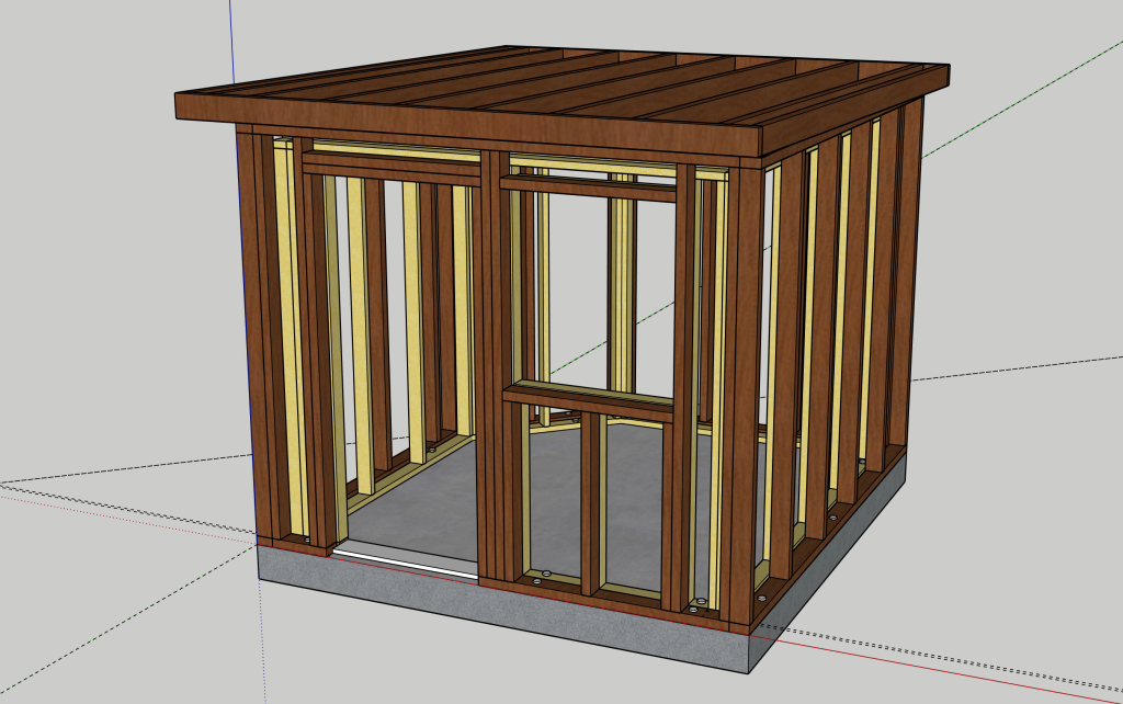
The interior and exterior timber frames sat on the concrete subfloor It will be 2.5 meters tall at it’s highest point at the front.
The internal space will be approximently 2.3m wide by 2.5m deep with a ceiling height of around 2.2m depending on the type of floor covering I decide to go with. That’s about 20cm lower than the ceiling height of a modern new build due to the second internal roof, however it will still be more than ample.
For soundproofing, I’m creating a “room within a room” — an internal stud frame set 2.5cm in from the outer frame, with bolts fixing the frame to the floor.
Using SketchUp, I modelled materials like plasterboard walls and OSB siding to estimate quantities, align stud work, and avoid awkward cuts.

Adding OSB sheets to the model, positioning them to optimise cuts and quantities virtually 5. Garden Room Wall Construction
External Wall:
- 2×4 timber (100mm x 47mm), studs spaced 600mm apart.
- Exterior layers: 18mm OSB → breather membrane → roofing battens → featheredge cladding.
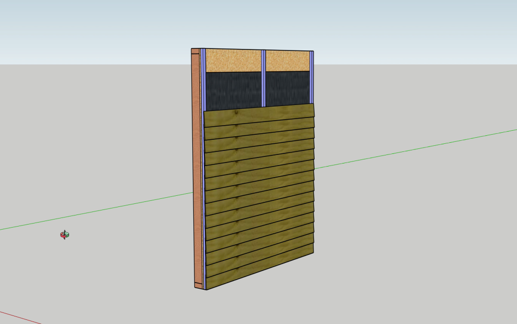
Cross section of the exterior wall Internal Wall:
- CLS timber (89mm x 38mm), spaced 2.5cm from the outer wall to create an air gap, also 600mm apart (at the centre).
- Interior layers: insulation → vapour membrane → two layers of 15mm soundproof plasterboard.
The finished wall thickness will be about 30cm.
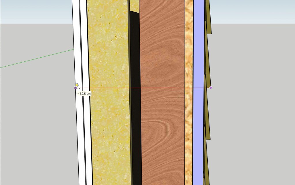
Total width of the planned wall structure Conclusion and Next Steps
Do your research and plan in advance. If you following the guidelines for permitted development and building regulations in your garden room design, depending on the size and function of the room, you can potentially avoid the need for approvals.
Use a free tool like SketchUp to design your space and calculate the materials you need, and draw out blueprints to make the construction process as straight forward as you can.
Follow the rest of the series on YouTube and this blog to see the step by step process I follow, and the completed room.
Products Used

SketchUp
Useful Links
Links to the UK Planning Portal resources:
Permitted Development https://www.planningportal.co.uk/info/200125/do_you_need_permission Building Regulations https://www.planningportal.co.uk/info/200128/building_control/38/building_regulations Building Control Part P – Electrical Saftey https://www.planningportal.co.uk/info/200135/approved_documents/82/part_p_-_electrical_safety